


Instruction Booklets
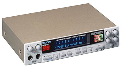
Operation manual (user guide) for the 9030 Advanced Instrument Effects Processor.
Tips and Tricks
to be added
Schematics and Service Manual
Schematics for Zoom gear of this era are nigh impossible to find, but the information below might be helpful.
FACTORY RESET
The manual only mentions how to restore ROM presets one at a time by using the Utility function. This is not only inconvenient, but not comprehensive because any other general settings (display brightness, etc.) are left intact. As such, the common tactic to doing a full factory reset is to remove the coin cell battery for a period of time to clear the memory, but this requires opening the 9030 chassis.
Fortunately, there is an undocumented feature called “SELF-INSPECTOR” which provides for an actual full factory reset without having to manipulate the battery.
– Turn off the Zoom 9030 by pressing the power switch.
– Hold EXIT + UTILITY and press the power switch.
SELF-INSPECTOR has various test modes which can be selected using the PATCH UP/DOWN buttons. The values within the currently selected test mode can be changed using the CHG UP/DOWN buttons.
The last test mode allows for a full memory wipe which clears all global settings and overwrites any user changes with the ROM defaults.
Other tests include RAM, LED, encoder, and display diagnostics.
HARDWARE COMPONENTS
BAT – CR2032
CPU – NEC 70320GJ
DSP – ZFX-1A (proprietary)
ROM – AMD AM27C020-155DC (IC9)
The firmware binary is available and can be written to a suitable 256KB EPROM.
DISASSEMBLY
– Remove six screws total (two per side) from right, left, and rear.
– Lift and remove the metal cover.
– Remove three black screws from MIDI and remote jacks on rear of unit.
– Remove five silver jack nuts from rear.
Note: Special care should be taken not to mar the paint when removing the jack nuts! Use masking tape or some other method to protect the surface, if needed.
– Remove four screws total (two per side) which retain the display assembly.
Note: Do not attempt to fully remove the front panel/display assembly. It is attached to the mainboard at multiple points.
– Disconnect CN2033 and CN2031 connectors attached to the PCB-0040 daughtercard.
Note: Grip the connectors by the plug and not the wires! Tweezers may be necessary.
– Remove two screws from PCB-0040.
– PCB-0040 should then be removed by lifting vertically. In other words: Pull exactly straight-up, not at an angle.
– Remove two screws from mainboard which are located closest to the side with the power jack.
– Remove two metal standoffs from the mainboard located on the side opposite to the screws in previous step.
At this point, the mainboard and the front panel/display assembly can be slid forward out of the chassis. The mainboard and front panel should be treated as one piece, and should be moved out the front of the chassis by gently pushing on the rear jacks while gripping the front panel and mainboard together.
The majority of the components are accessible without further disassembly, although the bevel for the front panel can be removed to access the encoders, buttons, display glass, etc. There are two screws on the bottom of the front panel, as well as retaining tabs.
HARDWARE TROUBLESHOOTING
DISPLAY
It is possible to turn down the display brightness to the point that nothing can be seen. While this is an unlikely issue, it’s worth exploring if someone could have inadvertently changed the setting.
More likely, there is a hardware fault. There is a glass cartridge fuse on the back of the display which may have blown.
NO AUDIO
The most obvious thing to check is various inputs and outputs. If one input jack works but not the other then suspect that particular jack. Likewise with the outputs.
The 9030 will turn on and function without the PCB-0040 daughterboard installed. Some patches with a high amount of self-noise will even present hiss at the outputs, but no meaningful signal will appear. If “air” can be heard but the input signal cannot be heard then PCB-0040 is worth investigating.
ONE AUDIO CHANNEL MISSING
The area around OP9 (4558 dual op-amp) on the underside of the mainboard deals with audio. It’s worth inspecting if one channel of audio is out, and the jacks have already been confirmed as working.
COMPRESSOR ISSUE
Look around OP10. This ZOOM 9030 repair blog gives lots of details.
SKIPPING ENCODERS