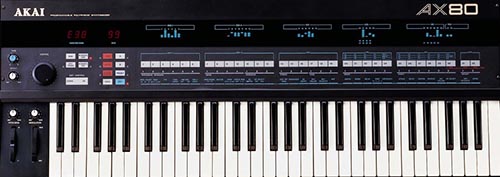
END USER INFORMATION
CHIPSET REFERENCE SHEETS AND OTHER TECHNICAL INFORMATION DOCUMENTS
Intel 8279 Display and Keyboard Interface, NEC uPD8279C
NEC uPD2764 EEPROM
NEC uPD446 RAM
NEC uPD8253C Programmable Interval Timer
NEC uPD8255AC Peripheral Interface
Texas Instruments (TI) 74LS293 4-bit Counters
Toshiba TC4050BP Hex Buffer
NEC uCOM 87 CPU Series Data Book
NEC uCOM-87AD CPU Series User’s Manual
NEC uPD7801 (Related CPU) Data Sheet
NEC uPD7810 CPU User’s Manual
SN74LS374 Address Latch
74LS00 NAND Gate
Curtis Electromusic – CEM 3372 Controllable Signal Processor (Voice Chip), 3372 Supplementary Info
Akai AX80 Service Manual (includes schematics)
TAPE OUT (FSK) INFORMATION AND UTILITIES
Akai AX80 FSK (tape in/out) encoding and decoding utility pack (currently designed for Windows command-line usage only): Direct Download
Simply run one or both of the included batch files.
Akai AX80 Tape Out (FSK) Format Information
The Akai AX80 frequency shift keying format (FSK) consists of two tones: A high tone centering at around 1958 Hz and a low tone centering around 979 Hz.
A “mark” (digital one) is two cycles of 1958 Hz (high) tone and a “space” (digital zero) is one cycle of 979 Hz (low) tone, meaning that each bit takes the same time to transmit regardless of whether it is one or zero. In other words, the AX80 maintains a steady baud rate where the time length of the FSK dump remains constant irrespective of the specific patch data. This is an expected and natural result of the high tone being exactly twice the frequency of the low tone.
Every AX80 FSK patch dump is approximately 60 seconds long, with the first 9 seconds consisting of the pilot/leader tone which is equal in frequency to the high tone of 1944 Hz.
The Akai AX80 communicates via asynchronous serial transmission with the highly unorthodox framing of 1 start bit, 8 data bits, no parity bits, and 8 (yes, eight!) stop bits per 17-bit word.
When each transmission is decoded into traditional 8-bit words, it should contain 2913 bytes.
Akai AX80 FSK File Format
After discarding the leader tone, the first meaningful byte is a header byte of $AA. The second byte transmitted is a (somewhat arbitrarily) user determined identification number which ranges from 0-29 (decimal) expressed in hexadecimal as $00-$1D.
The next bytes are actual user patch data with the first 1440 bytes being BANK A, directly followed by BANK B which is also 1440 bytes. Each bank contains 32 patches, and each patch is composed of 45 different parameters, each expressed by one byte.
After the patch data, there is one byte of junk padding which can be set to ’00’ so as to not affect the following byte which is a checksum. The checksum is an 8-bit (one byte) standard checksum which is calculated in the traditional manner of XORing each transmitted byte with the previous checksum value. The leader tone and $AA header byte are not included in the checksum-8 calculation, only the identification number, patch data (BANK A & BANK B), and garbage byte (usually null).
Concluding the transmission is a thirty byte trailer of straight $55 values. Like the leader tone, anything after the thirty byte trailer should be discarded and not considered part of the file format.
Akai AX80 (Rev. K) Factory Preset Data Cassette Tape (WAV file)
CPU/ROM/EPROM BIOS AND FIRMWARE SPECIFICS
In-depth information to be added at a later date, but related and generally relevant information is already available here.
Akai AX80 (Revision I) [December 1984] ROM firmware
Akai AX80 (Revision K) [February 1985] ROM firmware
Akai AX80 (Revision L) [?August? 1985] ROM firmware
Akai AX80 main CPU mask ROM
REVERSE ENGINEERING NOTES
Memory mapping, etc. to be added at a later date. Ready to compile assembly code will not be made available, sorry.


