


An augmentation to standard sound ROM hacking is EPROM bank switching. This method provides selection of four different kits on-the-fly instead of having to physically swap out single kit chips over-and-over, as–even with an external ZIF socket–this is tedious and prone to error and damage.
909, DMX, RZ-1, and 808 kits without repeatedly opening up the machine?
Four Bank Selection Hack
Additional Materials Needed:
Two SPDT sub-miniature switches (or an electrical equivalent such as a binary encoder)
Two 27C010 EPROMS (see addendum for details)
Two 32-pin leaf sockets (as caddies; highly suggested)
Also, if your RZ-1 does not already have sound ROM sockets fitted, SIPs are highly recommended. Please reference the addendum at the end of this article for clarification.
Note: The Casio RZ-1 uses two separate chips to store its sounds, so all steps have to be applied to both sound ROM A and sound ROM B.
Four 27C256 banks will fit on one 27C010, so choose four standard sized (27C256 type, 32K file size) RZ-1 sound ROM binaries which are designed for sound ROM A. Join those ROMs together into one file using a hex editor or the Windows command-line, such as:
copy /b 808_A.ROM + 909_A.ROM + DMX_A.ROM + RZ1_A.ROM 27C010_A.ROM
Do the same for the sound ROM B binaries (which should obviously be selected to match sound ROM A). The resulting ROM files should be written to the blank 27C010 EPROMs with an appropriate hardware programmer.
Note: Make sure the ROMs are joined in the same order for both sound ROM A and sound ROM B, or one half of the drum kit will not match the other half! Also, make sure to label which 27C010 is for ROM A and ROM B as the chip positions cannot be swapped.
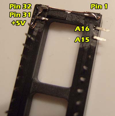
Next, carefully and gently bend out pin 3 of both 27C010 chips to approximately a 45 degree angle. WARNING: DO NOT BREAK THE PINS OFF!!!!
The 27C010 is a 32-pin chip and the original 27C256 is only 28 pins, so the new chips will not fit without a degree of surgery.
Pins 1, 2, 31, and 32 are going to overhang the socket** and not be connected to anything on the PCB. Pin 3 of the 27C010 is bent out so it will “miss” pin 1 of the socket. The rest of the chip should be fit normally into the socket. In other words, square up the end of the chip without a notch with the end of the socket without a notch; the notched end of the 27C010 will be dangling four pins beyond the notched end of the socket.
On the top-side of 27C010, bridge Pin 30, 31, and 32 and then jump a wire across to Pin 1. Make sure to do this across the top portion of the pins instead of the bottom because pin 30 needs to still fit in the socket. Pin 30 gets +5V from the socket and will thereby supply it to the overhanging pins to which it is now connected.
Again, this procedure must be done for both ROM A and ROM B 27C010 chips.
Pins 2 and 3 are where the magic happens; these are the extra two address pins that will enable access to four banks total instead of only one.
All that is needed to control the address pins are two SPDT toggle switches. The middle leg of one switch will go to Pin 3 (A15) and the middle leg of the other switch goes to Pin 2 (A16). Connect one leg of each switch to ground, and the other leg of the switch to +5V. But, to make this reliable and electrically sound, it is highly recommended to add pull up/down resistors before soldering the switch wires to +5V and ground. To do so, place a resistor at the end of all four switch wires which will be connected to +5V or ground. Connect the resistors to the end of the wire which is furthest from the switch itself. To clarify: Two resistors are needed per switch — one for +5V line and one for ground. Do not add a resistor to the middle leg, as that is connected to an address line. The resistor value should be 10K or lower, so 4.7k or 330 ohm are also easy to find candidates.
Possible Pull Up Locations
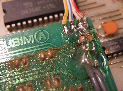
Possible Pull Down Location
The switches are shared between sound ROMs A and B, so wire ROM B in the exact same manner. Special attention is required, however, to make sure Pin 2 for ROM A and ROM B are going to the same leg of the same switch, and Pin 3 for both ROM A and ROM B are connected to the respective switch. In other words, when flipping a switch, both ROM A and ROM B should toggle the same address (either A15 or A16) at the same time — when ROM A A15 goes low, ROM B A15 should go low as well, and when ROM A A15 goes high, ROM B A15 should go high. A16 should behave likewise. If A15/A16 for ROM A are opposite in respect to ROM B then the RZ-1 will switch to mismatched kits.
As the switches control the various states of on/off, there are four unique combinations:
S1 S2
0 0 bank 1
0 1 bank 2
1 0 bank 3
1 1 bank 4
Switch placement is left to the discretion of the mod installer, but a suggestion is to drill two small mounting holes on the front left-side of the black metal base. This will prevent accidental physical exposure to the switches due to the overhang of the top chassis.
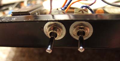
Toggle Switch Placement
For extra variety, it is possible to add another pair of switches (four total), and have ROM A and ROM B each wired to their own pair. This allows for independent selection of each half of every kit for sixteen distinct mix-and-match possibilities — for example: 808 ROM A with RZ-1 ROM B, or DMX ROM A with 808 ROM B.
NOTES AND AFTERTHOUGHTS ADDENDUM
SOCKETS
Clearly, if reprogramming the sounds is desired then desoldering the switches from Pins 2 and 3 will be necessary, as well as the jumpers between Pins 1, 30, 31, and 32. Pin 3 will also need to be unbent so it’s inline with the rest of the pins again — not terribly graceful. Which leads to…
Machine Pin SIPs
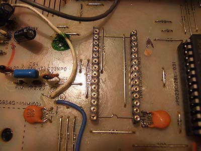
** an unaltered RZ-1 will not actually have a socket, but the PCB only has 28 holes, so the point remains. The above technique should be used if the RZ-1 has already been fitted with 28-pin sockets, or if one is planning on fitting 28-pin sockets during the mod, however, if your RZ-1 has not already been modded then a semi-permanent (and highly suggested) method would be to install machine-pin SIP sockets (two single rows of 14) on the mainboard, but use a (dual leaf/wiper type strongly advised) 32-pin socket as an adapter “caddy”. This way the caddy can be modified and wired up directly instead of the EPROM itself.
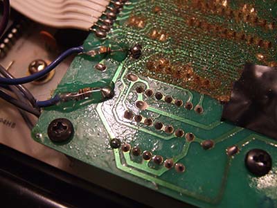
When modifying the 32-pin sockets, it is extremely helpful to take out the A16 and (most importantly) A15 wipers before cutting away some of the plastic material on the underside. This provides extra space to connect the wires leading to the switches and enables the sockets to sit flush. Simply re-insert the wiper pins after enough material has been removed. Refer to the picture below for which pins to connect, bent, and/or modify:
Sound ROM Socket Modification
This is the most adaptable method because any style socket (28 or 32 pin, dual leaf or machined) can be inserted into the SIPs, or the original ROMs can simply be placed into the SIPs to return to stock.
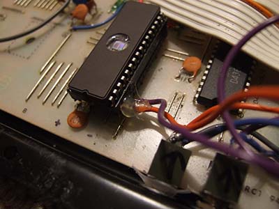
Final Result
EPROMS
While this article specifically states 27C010, 27C1001 EPROMs will work just as well. In fact, the RZ-1 is mysteriously particular about what brand/style of EPROMs are used. During testing, one type of 27C010 would work correctly as sound ROM B, but would introduce glitches if used as sound ROM A. Yet, the exact same data written to an ST M27C1001 performed perfectly — it’s unknown what subtle property is at play here.
It is suggested to test individual banks on 27C256 chips first to check for any pops, clicks, hum, or glitches. Once all four banks have tested fine as single banks, write the banks to a 27C010/27C1001. If any new anomalies are introduced then it is likely caused by that particular make/model of EPROM.
CHIP ENABLE VS. ADDRESS LINES
An alternate technique to using oversized ROMs is to add (often as a “piggyback”) extra EPROMs of the same capacity (27C256, in this case), but enable/disable an entire chip at a time using the chip enable (or chip select) pin. Commonly, one would bend out the chip enable pin on two ROMs, piggyback them, and then solder all pins together except the CE pins. Then the CE pins can be connected to a switch so that when one CE pin goes high, the other goes low. As opposed to the 27C010 method which provides quad kits, chip enable switching only provides dual kits.
However, it’s possible to combine both methods so that two 27C010 ROMs are piggybacked and address toggled. This gives 8 kits total with only 3 switches, or 64 kit combos if using 3 switches per ROM. The RZ-1 has an abundance of internal space, so this is quite possible to do. Speaking of an abundance of space…
PIGGYBACK PCB
It’s possible to create a piggyback which goes laterally instead of vertically. This employs the same concept as the piggyback ROM method except the ROMs are not physically stacked and soldered together, rather multiple ROMS (or sockets, ideally) are electrically connected on a PCB which plugs into the RZ-1 sound ROM socket just as a single ROM would.
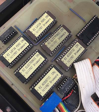
Drumware (Third Party) Expansion
Again, one could fit multiple 27C010 sockets on a single PCB (perfboard?), connect all corresponding pins together (except for the chip enable pins), and then connect a rotary switch to activate only one ROMs chip enable per switch position. The rotary switches between chips, and the toggle switches still control the address lines.
ADAPTER PCB
Same concept as the piggyback PCB except instead of multiple 27C010 sockets, the PCB electrically connects a higher capacity EPROM with even more address lines. This higher capacity EPROM would be too physically different to ordinarily drop-in (even the 27C010 needs a bit of modification!), so all the signals are re-routed appropriately by the PCB. Each additional address line will double the amount of kits, but will also need an additional switch.
This is the exact same concept as the 27C010 method, just with EPROMs of even higher capacity (and therefore increasingly different physical layout).
ULTRA-ADVANCED HACKING
The ultra-advanced sound hacker can go a step further and alter the program ROM with custom sample lengths so that sounds which are longer than the equivalent stock drums can be used instead, although obviously the total available space per EPROM remains the same — for one sound to be longer then others must be shorter by the exact same total amount. However, tightening up the toms and open hi-hat in particular will provide extra space for otherwise impossible sound replacements such as gated snares, extended 808 kicks, etc. Anyone wishing to pursue this high-degree of customization is advised to contact R-Massive directly, as it requires replacing the OS (system/program) ROM with one patched in a very specific manner.
Another drawback to this method is that pre-made kits will no longer align properly, so every sound ROM needs to be specially tailored to the custom layout.