The usual disclaimers about liability and damaging your equipment apply. Proceed at your own risk. Be mindful of static discharge and electric shock. The ASR-10/ASR-88 should NOT be plugged in or turned on while performing this modification!
The ASR’s DB25 SCSI port ordinarily does not carry SCSI termination power. Because of this, any SCSI storage device used normally has to be powered externally, or at least part of a SCSI chain which is externally powered.
This tutorial contains specific instructions on how to add SCSI termination power to the Ensoniq ASR-10 or ASR-88 keyboard samplers. One of the biggest benefits to doing this easy modification is that SCSI2SD/ZuluSCSI users will no longer need to use an external source (such as microUSB) to power the SCSI unit. This is particularly applicable to SCSI2SD v5.5 or ZuluSCSI Mini because then it can be used in true “cartridge” fashion–just plug and go!
These instructions should be accurate if the ASR is stock. If the SCSI card in the ASR is an aftermarket model then it is possible this mod has already been installed, or can be achieved in a slightly different manner. The only requirements for performing the modification are a schottky diode (about $3 if you have to order one), a phillips screwdriver, a soldering iron, and solder.
The choice of diode does not have to be exact, but a 1N5819 1A 40V Schottky diode is a reasonable choice, and has been tested to work.
The task is relatively simple: Disassemble the sampler (rack or keyboard), gain access to the SCSI daughtercard, solder a diode to the proper two points, and then reassemble the ASR without breaking anything. It’s not super difficult, but do take care. Refer to the technical notes and picture below for clarification.
Mentally double-check all the work before firing this up. If you think you forgot anything, or think the soldering was sloppy then remedy it before turning the ASR on! If everything was done properly, you should find that many more SCSI devices will work correctly with the ASR sampler.
Disassembling the ASR doesn’t require any special skills, but it does require care and patience. Consulting the Ensoniq ASR Service Manual is highly advised.
Technical Notes
This DB25 port connects to the SP-3 SCSI card on a 26-pin header. Specifically, pin 25 of the DB25 port connects to pin 24 of the 26-pin header.
Note: This header is labelled as “J1 – REAR PANEL SCSI CONN.”
Pin 24 of this header (J1) does not carry SCSI termination power, but the SCSI card does have a 5V source which can be used to supply SCSI termination power via pin 24 of this SCSI header (J1) which then passes to pin 25 of the DB25 SCSI connector. This is what allows the modification to work.
VCC (+5VDC) is conveniently available at a point physically close to pin 24. The part labelled RP3 on the SCSI card is a resistor pack, and pin 8 (the end closest to the RP3 text) of RP3 is VCC.
Solder a 1N5819 diode (or similar) from this VCC (+5VDC) point on the SCSI card to pin 24 of the 26-pin SCSI header (J1).
Important: The diode must have its cathode (banded/striped end) at pin 24 of J1, and its anode at pin 8 of RP3!
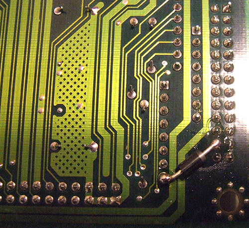
The diode is best attached from the bottom side of the SCSI card which has no text markings, so take care to visualize the pin numbers properly, and that everything matches the picture below.