The trick to doing so is the LTC1799 chip made by Analog Devices. Have the LTC1799 control the percussion clock, and then an add a knob to control the LTC1799 clock.
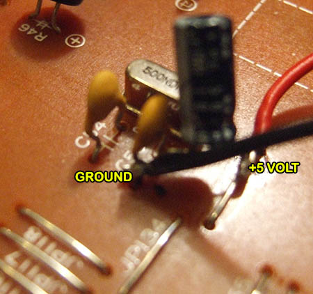
LTC1799 circuits need three things from the R50: power, ground, and a clock point.

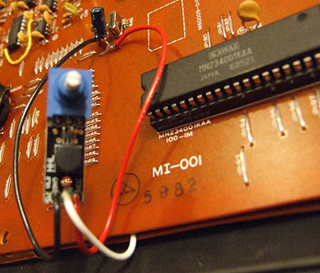
Top Side of the Mainboard
Power and ground can be taken from nearly anywhere, but these are easily accessible and tested points on the top side of the R50 mainboard with minimal soldering risks.
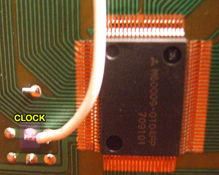
Unfortunately, the percussion clock (marked X2 on the PCB) can only be soldered to from the underside of the mainboard, so the mainboard needs to be removed first. There is also an RF shield which needs to be gently flexed out of the way.

Bottom of Mainboard
With the R50, the LTC1799 can simply be connected to this illustrated clock point; it is not necessary to remove the clock. In fact, leaving the clock in place has the advantage of being able to toggle between using the LTC1799 clock and the standard clock which has the effect of enabling or disabling the pitch mod.

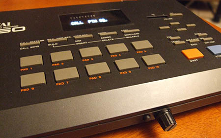
Mounting point is left to the user. Some people want it on top, some on the side, or some on the front. Given the placement of clock, the right side is the easiest, but do pay attention to how the case must fit back together and that there is enough clearance for the pieces to fit once fully reassembled. Using a step drill bit will add a dash of professionalism to the install, although normal drill bits can certainly suffice.
Note: Drilling holes in the R50 case is the most important step as it is not reversible. Triple-check all measurements and placements before committing.

Finished Result
The traditional source for LTC1799 kits is GetLoFi, but multiple options exist:
https://handheldlegend.com/products/variable-clock-ltc1799-linear-module
https://store.thursdaycustoms.com/product/variable-clock-v1
https://www.circuitbenders.co.uk/forsale/LTC/LTC.html
Center Square Music (with course and fine pitch adjustments)
The one from HandHeldLegend has the disable/enable switch already, and was used as the example for this guide.


