


This is a guide on how to add a toggle switch to optionally defeat the built-in noise gate feature on the Korg Poly-800 (original mk1 model) synthesizer. Doing so requires modifications to the hardware, but is non-destructive and can be easily reversed, if desired.
REASONS TO DISABLE THE POLY-800 NOISE GATE
Like any noise gate, the Poly-800 noise gate does not truly eliminate noise, but rather just mutes the audio path when the signal drops below a certain threshold. In the case of the Poly-800, this muting can be abrupt and cause “spitting” and “fizzing” type noises in the decay tail, especially on patches with long, gradual release settings. This effect can be more distracting and jarring than the noise it is intended to conceal, as the contrast between noise and signal is actually made more evident.
Also, in a studio setting, modern noise reduction solutions (iZotope RX, et al) work exceptionally well, and can mitigate or even totally eliminate all noise throughout the entire signal rather than just hoping a strong signal will mask any noise present until the gate clamps down without subtlety.
Lastly, even in a performance setting, defeating the built-in noise gate allows for other real-time noise suppression to be used, most of which will be more configurable and effective than the synthesizer’s own hardware.
PRACTICAL APPLICATION OF THE NOISE GATE MOD
– Locate R80 from the top side of the Chorus PCB. Note the position of its “bottom” leg.
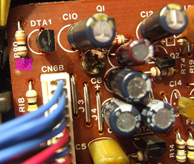
Bottom leg is shaded in purple
– Carefully disconnect CN6 and unscrew the Chorus PCB to allow for its removal.
– Locate R80 from the under side of the Chorus PCB. Desolder the “bottom” leg of R80.
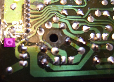
Bottom leg is shaded in purple
– Lift the “bottom” leg of R80. Connect a wire to the hole where the “bottom” leg of R80 was, and then connect that wire to the left side of a two position switch. See the orange wire in the picture below.
– Connect the middle of the two position switch to the “bottom” leg of R80. See the blue wire in the picture below.
– Connect the right side of the two position switch to ground. The RF shield behind the Chorus board is an ideal place for this, as it already has a solder point where another ground wire is already attached. Using the proper grounding point is important!
Warning: Do *not* attempt to use the keybed chassis as the switch grounding point! Although seemingly convenient, the keybed ground is at a different potential from the rest of the Poly-800 circuit, and the modification will not work!
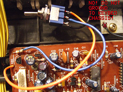
DO NOT CONNECT GROUND WIRE TO KEYBED!
– Screw the Chorus PCB back to the front panel, and reconnect CN6.
When the two position switch is flipped toward ground then the noise gate will never activate, as is the purpose of this modification. When the switch is flipped in the opposite direction, the noise gate will be once again controlled by the Poly-800 circuit, and will activate normally.
The switch can either be mounted on the outside of the Poly-800 case for easy noise gate selection, or tucked away inside the case for semi-permanent noise gate behavior.
THEORY OF THE NOISE GATE MOD
Note: This section is mostly academic, and might only be of interest to the technically minded.
The noise gate circuit is located on the Chorus PCB, but is actually controlled by a signal on the mainboard. Specifically, IC15 (TC40H174) pin 7 changes from 0V when the signal is allowed to pass, to 5V when the gate is activated. The CN6 connector passes this signal from the mainboard to the Chorus PCB on pin 2.
Once the noise gate control signal enters the Chorus PCB, it passes through R80 which then affects DTA1 (DTA114N). DTA1 is a transistor which opens and closes the gate of the F1 (2SK381) audio muting n-channel JFET.
F1 receives the audio input on its drain, outputs the audio signal on its source, and the amount of audio signal which is allowed to pass through the JFET is controlled by its gate voltage.
Note: The “gate” terminology can be quite confusing here because a JFET has a “gate”, but the JFET is also serving as a noise gate in this particular application.