


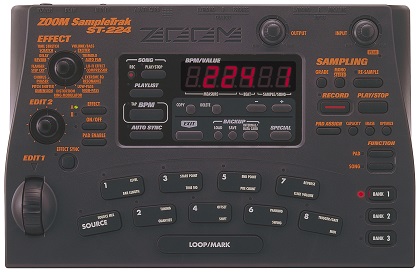
A bunch of fun stuff for your SampleTrak.
User Manuals
English
German
French
Italian
Japanese
Spanish
Utilities
ZMF Producer (with help file)
Zoom SampleTrak ST-224 Velocity Controller
Sounds
Factory Sample CD (WAV format)
ZMF Library
Demonstrations
Power Adapter
The official AC to DC adapter is Zoom AD-0006A, but AD-16A/D is another Zoom adapter which can be used as a replacement. However, there is nothing particularly special about the Zoom brand options, and nearly any DC adapter which is 9V DC, negative center, and 300 mA (or higher) can be used. In fact, a 10V adapter is also safe to use as the ST-224 has an internal voltage regulator.
Usage Tricks and Tips
Factory Reset / Initialize / Reinitialize / Restore
Warning: This wipes any user data stored in flash memory and replaces it with the factory samples!
– Power off the SampleTrak
– Hold the SAVE key and power on the SampleTrak
– The SampleTrak should show “init” on the display
– Press the EXIT key to abort, otherwise press SAVE again
Truncating Samples
After setting the start and end points of a sample, any unused portions which lie outside the two points can be removed using the Optimize feature. This is commonly known as “cropping” or “truncation” although the manual does not reference it by those terms.
Precision Editing of Start/End/Loop Points
There’s no need to struggle with trying to barely nudge the EDIT 1 wheel in an attempt to fine tune selections.
First, use the EDIT 1 wheel for course selection. Second, hold SOURCE while still using the EDIT 1 wheel and the selection number will only move in increments of 100. The + and – buttons can be used if the utmost precision is required.
SampleTrak as Effects Processor
The ST-224 can be used as an effects processor with any other audio gear.
– Hold EFFECT ON/OFF and then hit LOOP/MARK to set to ‘ON’
– Hold PAD ENABLE and press SOURCE pad to route inputs through FX DSP
– Hold SOURCE and then hit LOOP/MARK to permanently engage pass-through
Note: While the Source Mix feature provides for pass-through from the inputs to the outputs, the resulting signal bypasses the effects processor and is 100% dry and also cannot be panned. Since the effects can be disabled when using the above technique, Source Mix is essentially a redundant feature. Confusingly, it is possible to engage Source Mix while the input is already routed through the effects processor which results in a potentially unintended wet/dry blend.
Sampling Through Effects Bus
Use the effects processor technique as above, but with RE-SAMPLE engaged during the initial sampling. This prints an effect directly to a recorded sample without an additional round of resampling. It is usually best to print effects such as EQ and distortion directly into the sample, and only apply time-based effects (such as reverb or delay) during playback, as multiple samples can be routed through the same reverb effect simultaneously without taking up any extra recording time — this also ensures that all samples occupy the same “room” or “space” by using the same reverb parameters.
Create a Sub-Mix For External Effects
While the ST-224 has a respectable amount of effects at its disposal, some specialty effects like vocoder can only be achieved with outboard processing. It is ordinarily not possible to apply outboard effects to only certain samples while leaving the others untouched. However, there is a workaround which essentially gives you a dry bus, wet bus, and an aux bus.
– Set the panning for all pads (including SOURCE) to hard left [dry bus]
– Set the SOURCE pad to pass-through (LOOP/MARK + SOURCE)
– Set the internal effects to the desired algorithm and parameters
– Use PAD ENABLE to set any pads to the internal effects [wet bus]
– Set the panning to hard right for samples going to external FX [aux bus]
– Run the right output of the ST-224 to the external FX unit
– Run the output of the external FX to a mixer/DAW
– Run the left output of the ST-224 directly to a mixer/DAW
The trade-off is that everything gets collapsed to mono, so stereo imaging is lost. Another drawback is that the following internal effects do not respect the panning settings: Reverb, Dimension, Distortion, and (if crackle is used) Lo-Fi.
The same approach can be used to track two separate signals to a DAW for further processing; the only difference is that the external effects and/or mixer can be optionally omitted. The panned channels instead go directly to two mono tracks within a DAW.
Resample With External Effects Loop
Very similar to the above technique except the right output gets looped back (presumably after passing through outboard gear) into the left input of the SampleTrak. The input gain knob can be used to overdrive the signal, if desired. Although this is resampling in concept, the RESAMPLE feature should not be engaged during this process.
Warning: The SampleTrak will detect if only the left output is being used and it will sum left and right back into mono. This will cause either a screeching feedback loop, or comb filtering — both of which sound terrible! It is critical to use the right output, or both left and right outputs simultaneously.
Pro Tip: Inserting a “dummy” plug into the unused left output is a safe way to ensure that the outputs are never summed back to mono. This isn’t absolutely necessary if the panning is set exactly as described, but still a handy trick to keep in mind if any feedback issues arise!
Likewise, inserting a “dummy” plug into the right input is a solution to the summing issue when SOURCE has not been panned hard left.
Computer Based Workflow
It is possible to use the SampleTrak as a way to add character while sampling, yet still use a computer for precise and quick sample editing.
– Record samples at the desired quality with the SampleTrak
– Save all unedited samples to the SmartMedia card
– Use ZMF Producer to export the samples on the SmartMedia card as WAV files
– Chop, fade, or otherwise process the WAVs in an audio editor such as Audacity or Recycle
– Use ZMF Producer to import edited samples and assign to pads, pitch, pan, etc.
– Save full bank back to SmartMedia card and import into ST-224
Technical Details
While it is almost certain that schematics exist for the ST-224, unfortunately none have ever been released to the public. This collection of reverse engineering notes serves in lieu of a proper service manual.
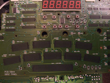
Disassembly
The SampleTrak is quite easy to take apart, and requires no specialized tools.
– Pull up on all four front panel knobs to remove them
– Remove the screw next to the MIDI input jack
– Remove six screws from metal plate on bottom
– Remove metal base plate
– Remove five screws from main PCB
– The main PCB lifts up and slides out at an angle
– Remove twelve screws from panel PCB
– Lift panel PCB to access display, pads, and buttons
All parts of the machine can now be accessed without disconnecting any of the ribbon cables.
During reassembly, make sure no loose wiring is near the EDIT 2 wheel; otherwise its motion may become restricted. Likewise, make sure the EFFECT knob wires do not become trapped under the panel PCB as this can negatively affect pad response. Only tighten the screws until they are snug; over-torquing them may break the plastic standoff posts.
Pad/Button Cleaning
Once the SampleTrak has been fully disassembled (see above), remove all three rubber button sections. The pads are fairly durable, but do not clean them with abrasives or other chemicals; warm water should suffice.
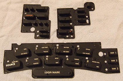
Remove any debris from the panel PCB contacts using a soft cloth. During reassembly, make sure all rubber pads are aligned properly on their guide posts.
Realtime Pitch Mod
The DSP in the SampleTrak is timed by its own dedicated 16.384 MHz crystal (X2) which means it can be reclocked by an LTC1799 for on-the-fly pitch bending and other sampling trickery.
Although the SampleTrak does allow for individual pitch control of each sample, this modification allows all sounds and effects to be sped up or slowed down at once. This is especially useful for live performance and/or glitch based music.
Solder the 5V, ground, and clock connections of the LTC1799 to the three points illustrated below.
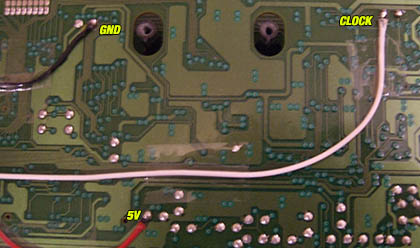
Use only these points!
There is limited space on the top panel or rear of the unit, so the pitch adjustment knob can be installed on one of the sides, or ideally the front edge if the pitch potentiometer and knob are small enough.
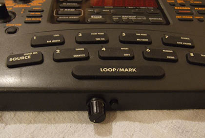
Pitch knob with on/off selector.
Power Regulation
The power supply provides approximately 9V DC, but other voltages are required inside the SampleTrak. The 9V power adapter connects to a very common DC barrel jack. The 9V is regulated down to a stable 5V which is required by some of the ICs (such as the DAC), as well as 3.3V which is required for the flash memory, SRAM, and SmartMedia circuits.
IC10 (C2251, NEC uPC2251H) — 3V regulator in a 4-pin TO-126 package
Pin 1 is input
Pin 2 is reset
Pin 3 is ground
Pin 4 is output (3V)
This regulator generates a reset signal which is needed to boot the processors.
IC11 (29M05, NEC uPC29M05T) — 5v regulator in an SC-63 package
Pin 1 is input
Pin 2 is ground
Pin 3 is output (5V)
Q3 (B962, NEC/Renesas 2SB962) — silicon power transistor in a TO-252 package
Possibly provides analog voltage supply for DAC/ADC.
C68/C69 are electrolytic capacitors which should be checked if power issues are suspected.
MIDI
IC1 (PC410) — optocoupler
CPU
IC5 (MN1021617CB) — Panasonic microcomputer in a 128-pin LQFP package
X1 — 30.00 MHz crystal oscillator, CPU clock
The CPU runs internally at 15 MHz which is half the clock speed. It likely boots from an internal program ROM which is encoded into the CPU itself and cannot be changed.
Effects Processor
IC12 (ZFX-2):
Inside the ST-224 is a proprietary, poorly documented digital 24-bit signal processor chip named the ZOOM ZFX-2. This 100-pin surface mount IC was also used for effects DSP in other ZOOM products of the same era, such as the 505, 506, 507, 508, 707, 708, 2100, 8080, and PS-02. While often utilized at a sample rate of 31.25 kHz, the 8080 runs the ZFX-2 at 44.1 kHz. Some Taito arcade games in the late ’90s used the ZFX-2 as well.
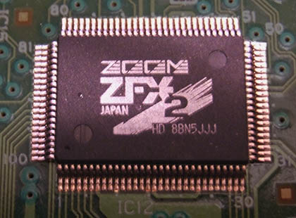
X2 — 16.384 MHz crystal oscillator, DSP clock
Flash Memory
IC4 (Sharp LH28F160S3T-L10A) — 16M-BIT flash memory in a 56-pin TSOP package
Non-volatile memory (NVRAM) which holds user data when saved to internal storage.
Note: 16 megabits is equal to 2MB which is the maximum file size of a ZMF bank.
IC28 (092-1001) — unknown memory in a 56-pin TSOP package
This likely holds persistent factory preset data which is restored during re-initialization. It is likely a read-only equivalent of IC4.
DAC & ADC
IC22 (PCM3001E) — Burr Brown 18-bit, stereo, serial CODEC in an SSOP-28 package
Three input voltages are required for IC22 to operate: digital voltage, ADC voltage (analog), and DAC voltage (analog).
RAM
IC3 (Toshiba TC55V328BJ-15) — 32,768-word by 8-bit CMOS static RAM (SRAM) in a 28-pin SOJ package; 15ns access time
Probably RAM for CPU.
IC13/IC27 (Panasonic MN4117405CSJ-06) — dynamic RAM (DRAM) in SOJ-24 package; 60ns access time
Probably RAM for sample data.
Other
IC6 (LV08) — quad 2-input AND gate in a SOIC-14 package
This is probably logic for the SmartMedia memory card interface.
ROHM BA410 opamps — various uses in analog signal path