


While only the 24 sounds within the currently active kit are available at any given time, kit selection can occur on-the-fly and does not require any rebooting of the drum machine.
Since the R-series provides for user definable presets, it is easy to create pitch/dynamics/pad layouts corresponding to each kit. All it takes is a few button presses to change to a preset, and then a flip of a switch to change to a new, perfectly configured set of sounds.
Interested? Here’s how to do it!
– Merge four 512K Kawai R-series ROM binaries into one 2MB binary. See the Kawai R50/R50E/R100 sound ROM page for sound ROM building tools and premade ROMs.
– Write the 2MB sound ROM binary to a blank 27C160 EPROM.
Note: Most EPROM burners do not support 27C400/27C800/27C160 ROMs without a special adapter. It is very likely that such an adapter will be necessary to write custom R-series ROMs.
– Overhang the sound ROM socket so that the EPROM end with the notch (pin 1 and 42) is not in the socket, but pins 2 to 41 are in the socket normally. The original 27C400-type sound ROM is only 40 pin, so the two extra pins on the 27C160 are address lines which enable the bank switching.
WARNING: Do not insert the EPROM into the socket backward. Do not insert the EPROM with the notched end in the socket. See picture below!
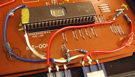
The middle leg of one switch (white wire) goes to pin 1 (A18) of the 27C160 and the middle leg of the second switch (blue wire) goes to pin 42 (A19). These are the pins which are not in the socket, as shown in the picture.
The other two legs of each switch go to ground and 5V. Although not strictly necessary, it is a good idea to use a resistor at these points. 4.7K is an acceptable value, but 10K and 330 are common resistor values which should also work. Convenient points for this are the metal jumpers on the top-side of the board: JP193 for ground and JP188 for 5V. In the picture, the red wires connect from the left-most switch legs to 5V, and resistors connect directly from the right-most switch legs to ground.
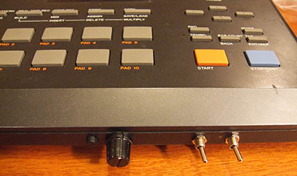
Possible Switch Mounting Positions
To mount the two switches, carefully drill two 1/4″ holes in the plastic case. If mounting along the front edge of the drum machine, it may be best to have the switches oriented horizontally as otherwise the bodies of the switches will likely not be flush with the casing. Do consider placement and spacing measurements before committing to any permanent alterations of the drum machine!
Just flip the switches between the four possible combinations to select between the four available kits.