


Since some form of altered firmware is required to accomplish this, the operating system binary provided for this method has the side-benefit of numerous feature upgrades such as OLED support and on-the-fly pattern changes.
Note: See the Casio RZ-1 custom firmware article for a full description of newly added capabilities.
Due to the required removal of multi-pin ICs, this modification requires above average desoldering ability and should not be attempted without prior success at similar repairs and/or modifications. The use of a professional desoldering tool, rework station, and/or Chip Qwik is highly recommended although not strictly necessary.
Use liberal amounts of flux where applicable.
Required Materials
– NEC uPD7810 64-pin CPU
– 47Kohm resistor
– at least 64 SIPs (2.54mm pitch sockets) [for CPU]
– 27256 EPROM + EPROM burner + custom binary (or a pre-burned EPROM)
– DIP28 leaf wiper socket [for EPROM]
– Kynar or similar thin gauge hookup wire
– soldering/desoldering tools
– needle-tip flush cutters
– needle-nose pliers
Download
– Casio RZ-1 CPU replacement EPROM binary and instructions bundle
Procedure
It should be obvious that the RZ-1 will need to be partially disassembled to complete the CPU replacement. It is good practice to mark any connectors and ribbon cables on the mainboard with their proper location and orientation, as they will need to be disconnected to gain access to the underside of the PCB.
Please take adequate safety precautions including but not limited to ESD protocols.
CPU AND 64K EXTERNAL MEMORY MODE FIX
– Prepare the 7810 by bending out pin 29 (MODE0) to a 90 degree angle. Tin both pin 29 and pin 63. Solder a 47K resistor from pin 29 to pin 63. It may be helpful to first hot glue the resistor onto the top of the CPU so that it remains stationary during soldering and while bending the leads to suitable positions. Reference “modified 7810 CPU” and “CPU pinout diagram” for clarification.
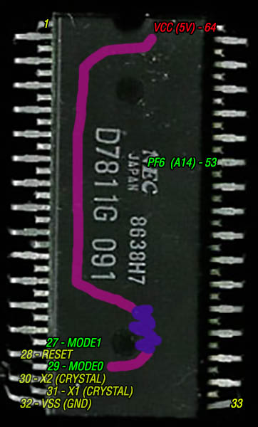
CPU pinout diagram
Note: Either pin 63 or pin 64 can be used here, but pin 63 is on the outside row which is more accessible. This works because pin 64 and pin 63 are connected via the RZ-1 mainboard, so pin 29, 63, and 64 will all receive 5V once socketed. Do *NOT* bend out pins 63 or 64!
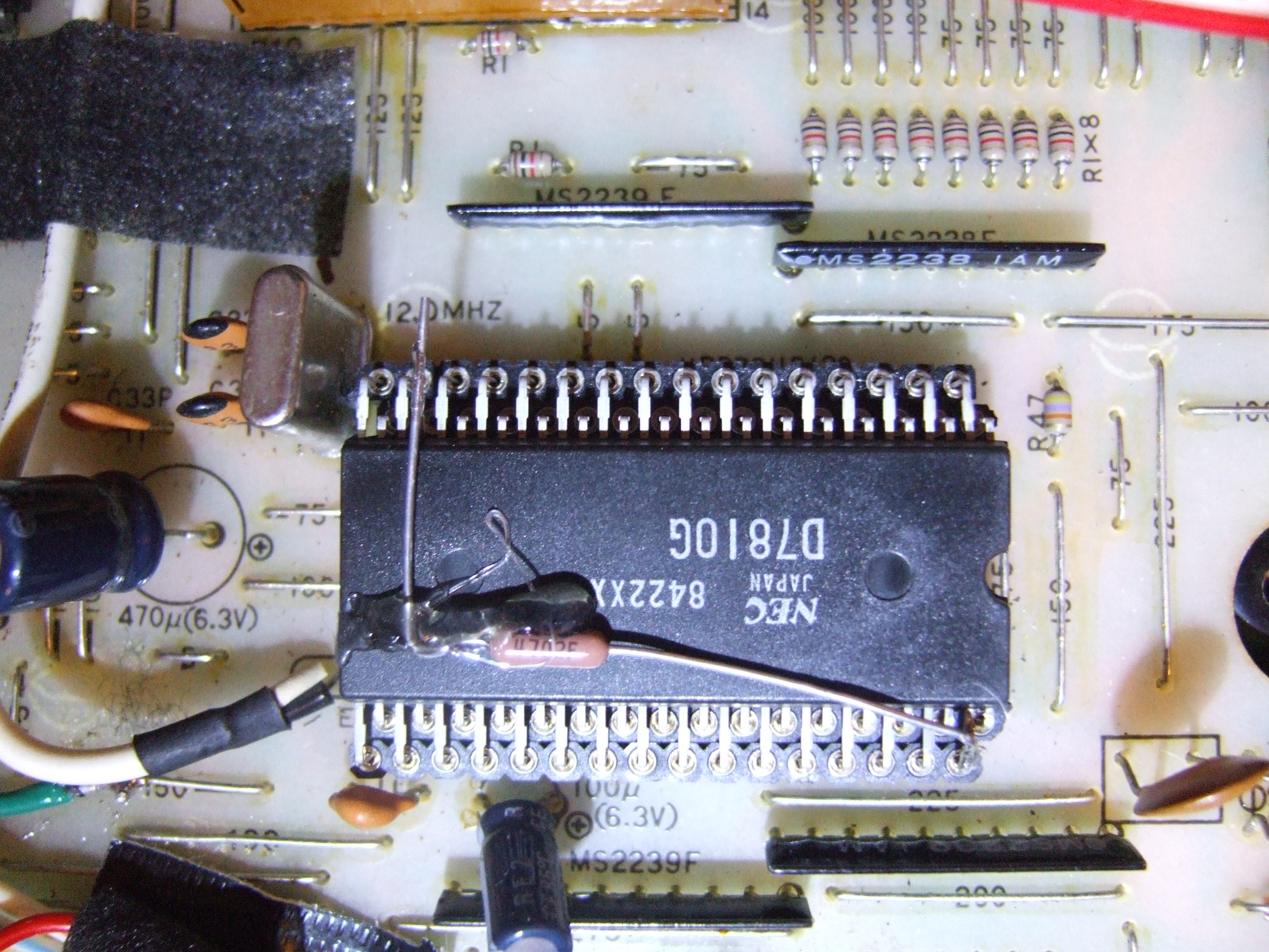
modified 7810 CPU
– Desolder the Casio RZ-1 7811 CPU. This is by far the most difficult step of the entire replacement procedure as all 64 pins of the CPU must be done without damaging the PCB. Take significant care not to lift or tear any pads while removing the original CPU.
– Break off four rows of 16 SIPs (64 machined-pin sockets total). Reference “CPU socket” for proper alignment, but do *not* yet solder it to the PCB.
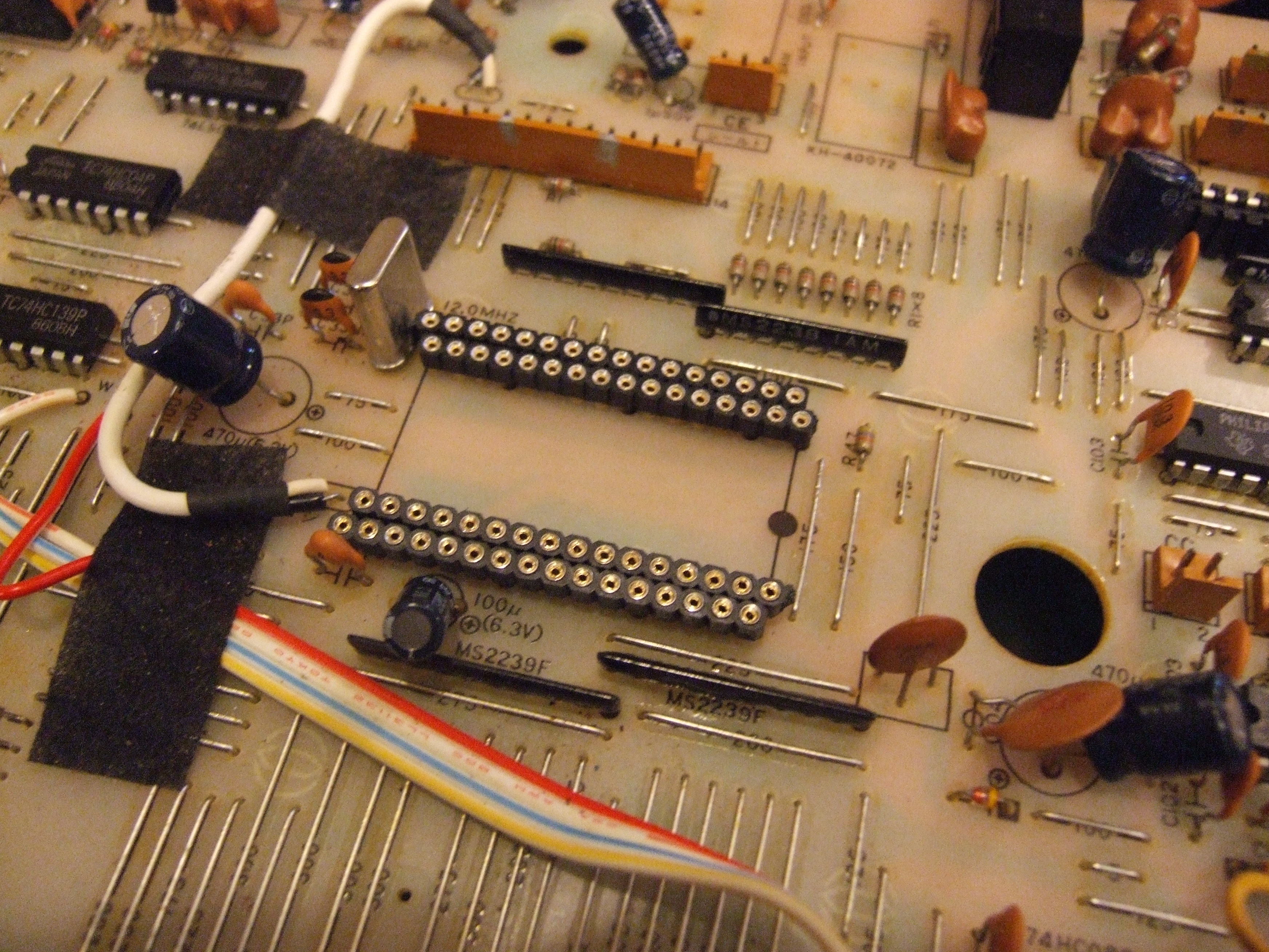
CPU socket
Note: The crystal canister to the immediate left of the CPU makes for a tight squeeze. It may need to be gently pushed to the side, and/or the SIP closest to it may need its edge to be filed down very slightly.
– Fit the CPU into the four rows of SIPs and then solder the SIPs into the mainboard. The CPU is oriented “upside down” (180 degrees of rotation, more properly) compared to the majority of the other chips, so double-check its orientation! See “modified 7810 CPU” and compare both notch and the silkscreened text on the CPU, if there is any doubt.
Note: Although it is entirely possible to solder the SIPs and then fit the CPU after, it is highly advisable to firstly fit the CPU into the SIPs and then secondly insert and solder the SIP/CPU combination into the mainboard as one unit. This facilitates checking that all CPU pins (aside from pin 29) are properly socketed, as all the pins can be investigated from multiple sides and angles. Checking the CPU pin-by-pin using a flashlight can be helpful.
OS ROM AND ADDRESSING FIX
– Either burn a blank 27256 EPROM with the supplied custom binary, or otherwise obtain a programmed EPROM from someone with the capability to do so. This EPROM combines the CPU mask ROM with a modified version of the operating system ROM which initializes the CPU to the proper memory mode.
– Bend out pin 27 of the 27256 EPROM at a 90 degree angle and then tin it with solder.
– Desolder the operating system ROM from the mainboard. Solder in the DIP28 socket taking care to maintain the proper orientation. Use “uPD23C128E-031” as a visual reference, if necessary.
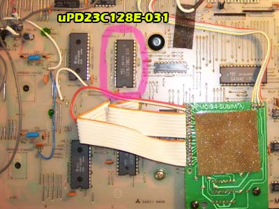
uPD23C128E-031
Note: The notched end (pin 1) of both the EPROM and the socket should be oriented in the same direction as the original OS ROM and the nearby sound ROMs.
– Fit the 27256 EPROM into the socket, making sure to maintain the proper orientation. Pin 27 will naturally “miss” the socket and overhang it, as it has been intentionally bent out to the side.
– At the bottom left of the CPU area, locate the nearby ceramic capacitor (C101). To the left and perfectly parallel to that capacitor there is a metal link labeled “150” (for reference, it is below a 470uF/6.3V electrolytic and above a link labeled “190”). It may be obscured by a piece of black tape which can be removed, if needed. See “A14 signal point” for clarification. Prepare the “150” link by tinning it with solder; copious amounts of flux may be required.
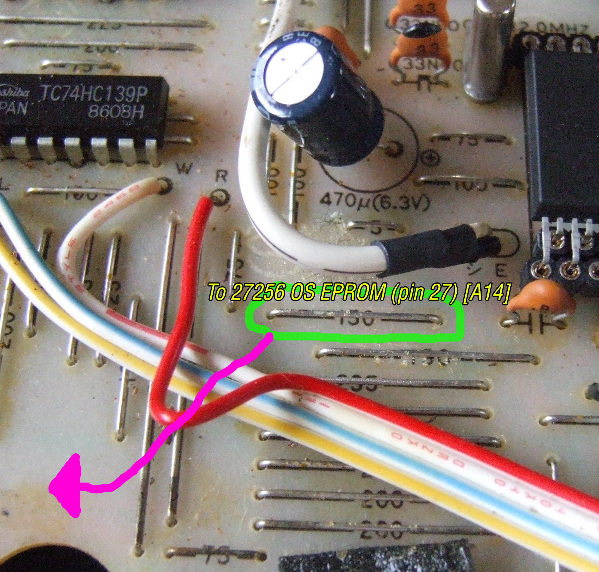
A14 signal point
– Solder a length of hookup wire from this “150” link to 25256 pin 27. Examine the green wire in “27256 (pin 27 to A14 signal)” for clarification.
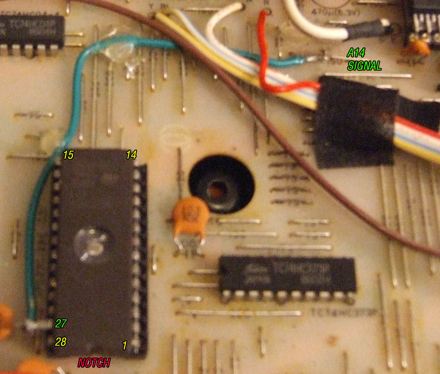
27256 (pin 27 to A14 signal)
CHIP ENABLE FIX
– Toward the left side of the mainboard, find the IC labeled TC74HC32P-2. Refer to “TC74HC32P-2” for a visual reference.
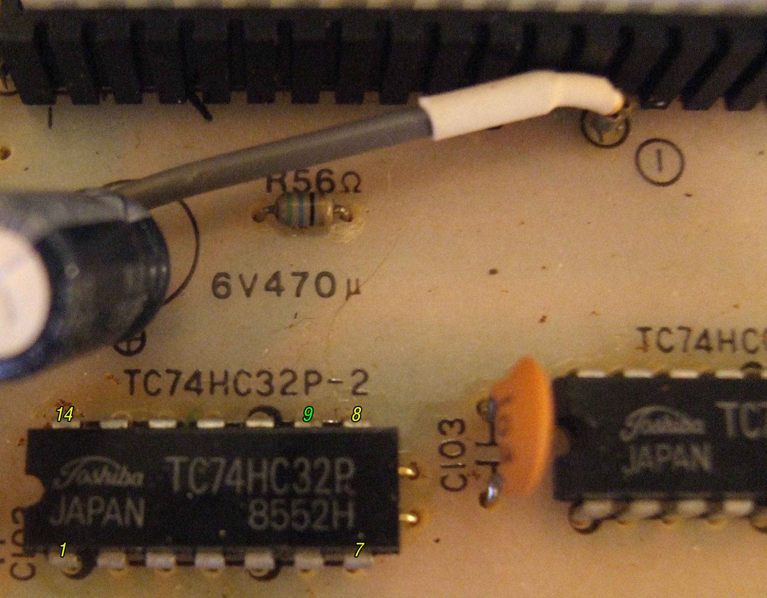
TC74HC32P-2
Note: There are two 74HC32 chips; one for READ, and one for WRITE. TC74HC32P-1 is for WRITE and is located next to 74HC32. TC74HC32P-2 is used for READ and is located up from sound ROM A (CM5). TC74HC32P-2 is correct, and TC74HC32P-1 should be ignored. Do not confuse the two!
– Using flush cutters, snip the bottom of TC74HC32P-2 pin 9 as close as possible to the PCB. Use needle-nose pliers to carefully bend out pin 9 to a 90 degree angle. Tin the pin with solder.
Note: It is also possible to desolder the entire chip, install a socket, and then re-insert the chip with pin 9 bent out to “miss” the socket. This method could be considered more graceful as it is reversible and non-destructive, but holds minimal advantage in this scenario.
– Next to the coin cell backup battery on the right side of the mainboard, locate 74HC27. 74HC27 does not need to be modified, aside from tinning pin 8. See “74HC27” for clarification.
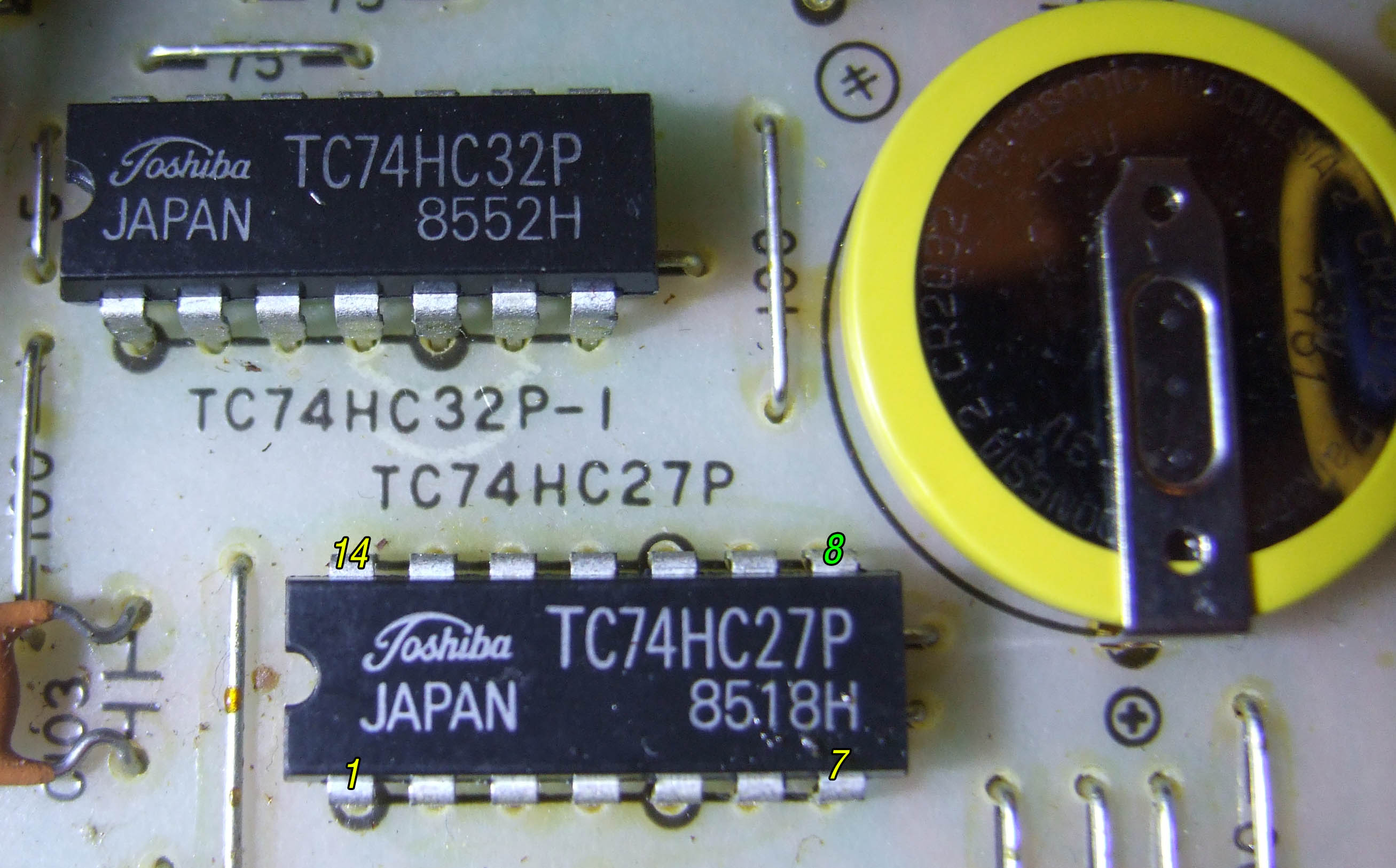
74HC27
– Solder a length of hookup wire from 74HC27 pin 8 to TC74HC32P-2 pin 9 (which should be bent out). The brown wire shown in “completed installation” illustrates wire routing possibilities, and the proper connection points.
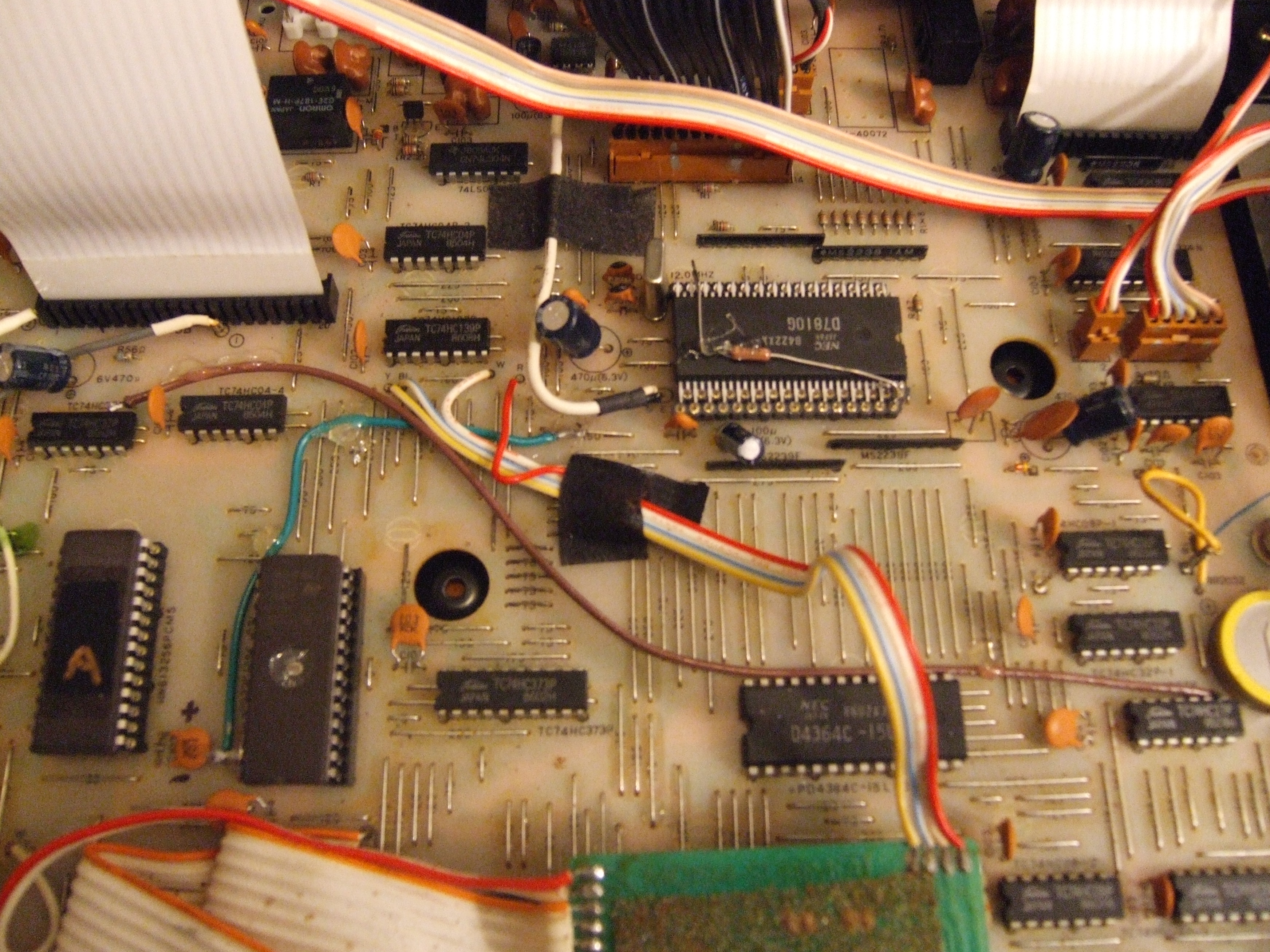
completed installation
TROUBLESHOOTING
– Carefully inspect all work before turning on the RZ-1, especially the CPU orientation! If everything matches “completed installation” then the procedure should be a success!
– Various problems will occur if any connectors and/or ribbon cables have been left disconnected or were mispinned upon reconnection. If the RZ1 boots but some pads will not sound, the headphone jack is dead, or the sampling input no longer works, etc. then this could be the reason. Likewise, it is possible to blow a fuse or cause another form of damage if any cables are connected improperly.
– If possible, verify the checksum of the EPROM. CPU ROM v2.0u should have a checksum-16 of [FA04].
– Make sure MODE0 is being pulled up to 5V.
– Use a logic probe to confirm that 27256 pin 27 changes between low and high during boot.
– It is very easy to overlook any of the 64 CPU pins for proper alignment while fitting the SIPs. Depending on the pin, this can lead to non-boot or seemingly random errors.
Technical Details
Note: This section contains supplementary information about how the method works on a technical level, and is not required (nor particularly helpful) reading for accomplishing the CPU replacement.
…full details to come…