The usual disclaimers about liability and damaging your equipment apply. Proceed at your own risk. Be mindful of static discharge and electric shock. The EPS16+ should NOT be plugged in or turned on while performing this modification!
This tutorial contains specific instructions on how to add SCSI termination power to the Ensoniq EPS16+ Rack (or Turbo Rack). These instructions are based upon the link below, which is mandatory reading if you want to proceed with the rest of these steps. These instructions should be accurate if the EPS16+ is stock. If it isn’t stock, then you likely don’t need this mod anyways. This mod requires a little bit of thin wire, a schottky diode (about $3 if you have to order one), a phillips screwdriver, soldering iron, wire-strippers, and solder.
** READ THIS PAGE BEFORE PROCEEDING **
http://www.chickensys.com/kb/eps-asr/004.html
Big ups to Chris Gandy and Alan Brown for the info!
Okay, now that you know basically what you are doing, and have your soldering tools and diode at the ready, you may begin. Our goal is to disassemble the rack case, gain access to the SCSI daughtercard, solder two wires and a diode to it, and then reassemble the EPS16+. Hopefully without breaking anything. It’s not super difficult, but be careful. I suggest you refer to the diagrammed pictures for clarification.
Step #1- Using a phillips screwdriver, remove the screws from the rack ears (if you have them), the back rim of the case, the sides of the case, and the top of the case. There are no screws on the front or bottom of the rack that need to be removed. Remember where they go. This isn’t too difficult, as most of the screws are the same.
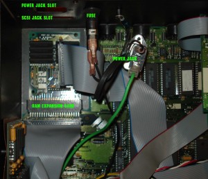
Step #2- Slide the case off the rack. Set it aside. Look at the back corner where the power cord jack is. Remove the two screws holding this in place. Move the jack out of the way to give yourself room to work.
Step #3- Remove the nuts and washers holding the SCSI jack in place. Move the jack out of the way without disconnecting its cable from the SCSI daughtercard.
Step #4- There are 4 long screws holding the SCSI daughtercard in place. Remove these.
Step #5- Gently as possible (there will be some resistance), and keeping the SCSI daughtercard as level as possible, lift the SCSI daughtercard vertically. LIFT STRAIGHT UP! There is a pin / socket underneath that connects the SCSI daughtercard to the RAM expansion board underneath. Be sure not to bend the pins. You should be fine if you DO NOT lift at an angle. You will see a black X-shaped plastic spacer. Remember which way it is oriented. One side of the plastic legs are taller than the other side. Note: While working with the SCSI daughtercard, be sure not to bend the long pins on the underside. They aren’t super-fragile, but take care not to bend them.
Step #6- There is a ribbon cable on the side of the SCSI daughtercard connecting the card to another larger card. As gently as possible, remove this cable from the SCSI daughtercard. Leave the other end of the cable connected to the larger card.
Step #7- This is optional, but I suggest you remove the SCSI ribbon cable from the SCSI daughtercard and set the jack/ribbon aside. This will make it a bit easier to solder stuff later on.
HERE IS THE POINT OF NO RETURN. IF YOU DON’T FEEL COMFORTABLE PROCEEDING, THEN ABANDON THE PROJECT, OR FIND SOMEONE CONFIDENT IN SOLDERING! TAKE ALL THE TIME YOU NEED WITH THE NEXT TWO STEPS!
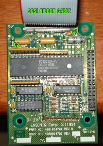
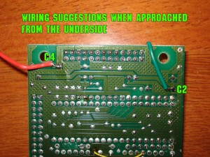
Step #8- Now that you can remove the SCSI daughtercard completely from the case, take a close look at the topside of the card. Up by the SCSI jack connector, there are two, small, yellow capacitors. One is marked C2, and one is marked C4. Looking at C2, identify the leg closest to the side of the card (the “left” leg). This is where we want to connect one of our wires. I chose to solder the wire to the underside of the SCSI daughtercard, but it’s okay to do it topside, if you feel you will be more successful. Using a fairly small gauge wire, trim a tiny bit of insulation off both ends. Smaller is better when it comes to the end we are going to solder to the card. Make sure your wire can be positioned in an appropriate place that won’t get in the way when you reassemble everything. I found it helpful to use some solder-wick to remove some of the factory solder from the solder point first to make for a cleaner connection. Pre-tin the wire and solder it to our C2 “left” leg position. Don’t use a whole bunch of solder, just enough for a good connection. Don’t make a solder bridge to any other traces or components.
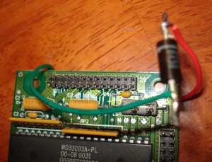
If you’re going by my pictures, then C4 is connected to the red wire. C2 is connected to the green wire.
Step #9- Looking at C4, identify the leg closest to the side of the card (the “right” leg). Using the same technique as before, connect another prepared wire to this position.
Step #10- If you’ve gotten this far without messing up, you’re pretty much golden! Connect the wire going from C4 to the -banded- side of the diode. Don’t reverse these, or your circuit will not pass any current. Meaning it won’t work!
Step #11- Connect the wire from C2 to the other end of the diode. Wrap any exposed diode or wire ends in electrical tape.
Step #12- Replace the black X-shaped plastic spacer to its correct orientation under the SCSI daughtercard. If you chose to solder the wires to the underside of the SCSI daughtercard, then make sure there wires have enough room to pass between the card and the spacer. You could carve a channel out of the spacer using an X-Acto knife, but there should be enough room, as is. Secure the spacer to the card using the 4 long screws, but only enough to keep the spacer attached to the card. Don’t turn them through all the way just yet.
Step #13- Making sure the pins on the underside of the SCSI daughtercard are properly aligned with the jack on the RAM expansion board, push the SCSI daughtercard back into its place on top of the RAM expansion board. Keep the board as level as possible to avoid bending the pins! Tighten the 4 long screws by alternating between each one, tightening each a little at a time. This will keep the pins underneath from bending, and the screw holes aligned properly.
Step #14- Reconnect the large ribbon cable to the SCSI daughtercard (and the SCSI jack ribbon cable if you chose to disconnect that one), making sure the pins are aligned with the ribbon plug correctly before using pressure.
Step #15- Reconnect the SCSI jack to the case using the washers and nuts.
Step #16- Reconnect the power cord jack using the two screws.
Step #17- Reassemble the case, returning the screws to their rightful place, and don’t forget those rack ears.
Mentally double-check your work before firing this up. If you think you forgot anything, or think the soldering was sloppy then remedy it before turning the EPS16+ on! If everything was done properly, you should find that many more SCSI devices will work correctly with your EPS16+ rack. Congrats!
The pictures below can be viewed at a much larger size by double-clicking the picture, and then double-clicking again.
Check the EPS 16 Plus SCSI manual for help with hard drive formatting instructions, etc. It’s hard to come by.


