


It’s a common thing to lose accessories, and a great many items are sold on the used market without instruction manuals, power cords, drivers (or other mandatory software), and adapters of various kinds. Some of these items can be found through the original vendor, third parties, or a generic equivalent, but all too often a seemingly minor cable can be all but impossible to find — at least at a reasonable price.
Such is the case with the Frontier Design MIDI breakout cable. The company used a proprietary standard for connecting MIDI in/out cables to their Dakota PCI card via breakout cable. They no longer sell it. There are also no substitutes from similar equipment to use, as the closest breakout cables you can find are 9-pin, not 8-pin. So what’s a person to do?
If only Google Images had X-Ray eyes
The easiest way would be to ask the company for the pinouts. In this case, it’s a no-go. No response from the company via user forum or email. Next easiest way would be to dissect a working cable to see what wires go to what pins. That would be great if you wanted to sacrifice a cable, or even had access to a cable at all (but if you already had a cable then you probably wouldn’t be worried about figuring out how to acquire another).
Only thing we’re left with is ingenuity, observation, deduction, and hopefully a multimeter. If you want something done right, better do it yourself. Let’s get to work.
MIDI breakout jack
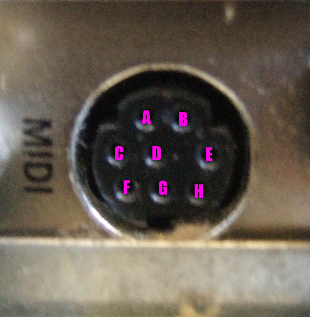
Looking at the MIDI breakout jack on the back of the Dakota PCI card, we can see it’s an 8-pin miniDIN style connector, most commonly used with legacy Apple computer (keyboard/mouse/printer) peripherals. That’s a good place to start for sourcing a cable to slice up in an attempt to make our own breakout cable, but it tells us nothing in regards to how a MIDI cable would be wired up.
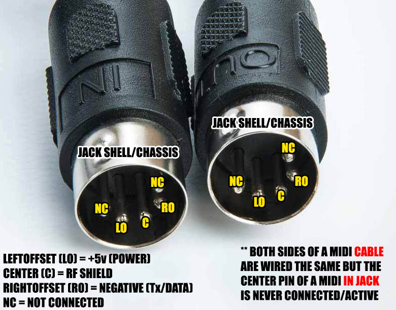
How MIDI cables are wired
If we reference the MIDI jack standards, we can see that there are 3 pins required per each OUT jack, and 2 pins for each IN jack. Each side of a MIDI cable has 3 wires connected, but our breakout cable is really a 2×2 jack (2 in/2 out) and not a standard cable, therefore the center pin on each IN jack is not needed. The difference between jack and cable is very important here. (Also, remember that a cable and a jack are mirror images of a sort, so wire up your breakout cable accordingly — if you’re looking at the bottom-right pin of a MIDI cable, that pin will connect to the bottom-left of a jack.) Adding up the amount of needed pins, we get a total of 10 — 3 out + 3 out + 2 in + 2 in. That seems like it’s going to be a problem if we’ve only got an 8-pin miniDIN to work with, but the designers used some semi-clever engineering to reduce the 10 pins down to 8.
Since the center pin of an OUT jack is used only for RF shielding purposes, it doesn’t need to carry any real signal. In other words, there’s no data that needs to be kept in its own “stream”. RME breakout cables approach this by using a 9-pin cable and combining the shield wires from both OUT jacks into one pin. That technique gets us down to 9 pins, but we still need an extra pin.
The trick here is that we don’t need a “pin”, per se. The shielding only needs an available ground, and the metal shell of the jack goes straight to the ground path of the PCI card. So if we combine the shield wires and route them to the jack ground, we’re left with 8 free pins — enough for the 2 signal wires on each of the 4 MIDI cables that will connect to the breakout cable.
Yeah, but which pin is which? Let’s look at the underside of the PCI card and see what we can visually identify.
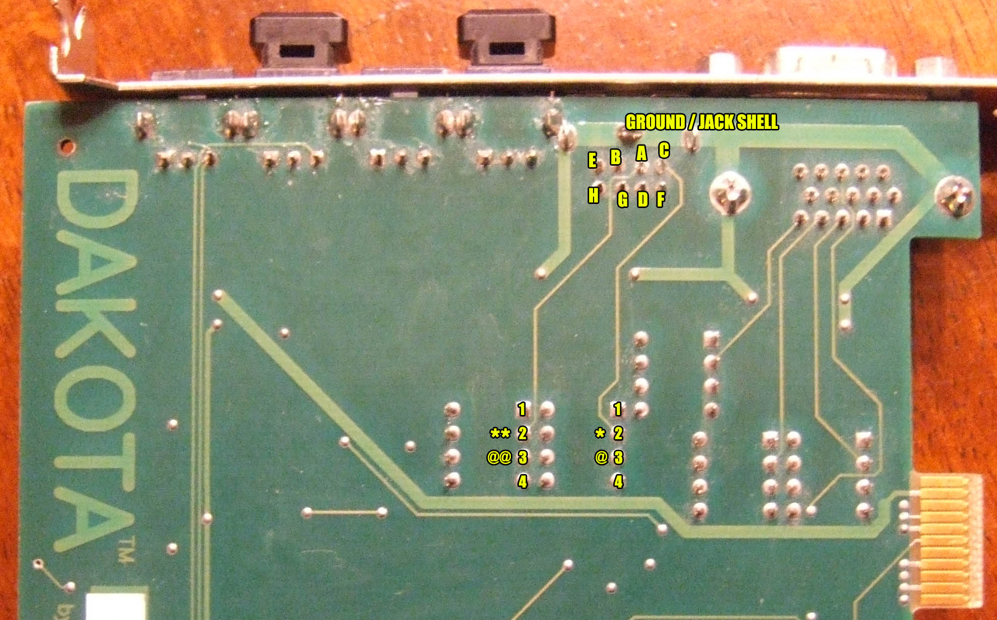
Find the jack, follow the traces
Two of those traces obviously go to specific IC chips, and those chips likely serve some MIDI function. But what?
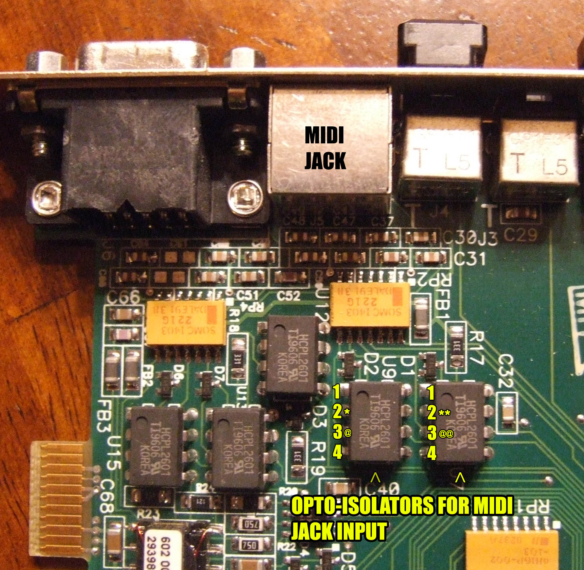
Examine the ICs connected to the MIDI jack
If we do some homework about MIDI IN port design, we’ll find out that each IN is supposed to go to an opto-isolator. If we look at the ICs that the traces went to, we’ll see that they are HCPL2601 chips — unsurprisingly, an opto-isolator. The pins that connect to each of those traces MUST be IN jack pins. Further referencing MIDI schematics, we can tell that the “LeftOffset” pin of a MIDI cable should hit a 220 ohm resistor before it hits the opto-isolator at the anode and “RightOffset” should hit the cathode.
If we reference HCPL2601 spec sheets, we can discover that the anode is pin 2 of the chip, and pin 3 is the cathode.
Even if we can’t confirm which trace/pin goes where strictly by looking at the PCB, we should still be able to use our multimeter to measure the resistance (ohms) between our jack pins and the 2 input pins on the opto-isolator. The jack pin with the higher resistance should be connected to LeftOffset.
What? In other words, we can look at the underside of the Dakota card and see that a trace leads from the MIDI port to an opto-isolator chip [HCPL2601]. Checking the schematics for the HCPL2601, we see that the trace connects to the anode of that HCPL2601 (i.e. pin 2 on the opto chip). The schematics also tell us that pin 3 on the opto chip is the cathode, so we measure the resistance from that cathode pin (pin 3 of that HCPL2601) to all the other pins at the MIDI jack. From the cathode on that HCPL2601 there are only two pins at the MIDI jack that should show any conductivity, one being the jack pin leading to the anode (easy to identify visually, incidentally) and then we should also see one more pin that shows conductivity, but the resistance is lower compared to the anode connected jack pin. The one with the lower resistance is the cathode connected pin and therefore the RightOffset pin for that particular MIDI IN port. The resistance really didn’t need to be compared in practice, because we already identified the anode, so the only other pin showing ANY connection to the cathode has to be the cathode pin, by default.
P.S. Pin 1 on the HCPL2601 chip can be identified by the “dimple” embossed on the top of the chip itself.
Since each of our two suspect HCPL2601 ICs correspond to one MIDI IN port, and we can tell which pairs of pins connect to each HCPL2601 chip, and we know which is the anode and cathode lead, then we have solved our MIDI IN ports! This also knocks our uncertain pins down to 4.
Again referencing MIDI specs, we know there should be one +5v line to each of the MIDI OUT ports. With the card powered on, use a multimeter to test each of the remaining 4 pins. The two pins that have a solid and steady +5v each belong to one of the OUT ports.
Only two pins left. Which belongs to port 1, and which to port 2 though? Fire up your sequencer and send some looping MIDI output to port 1. Use the multimeter to check the voltage of the two remaining pins. One of them should have fluctuating values. That’s port 1. The other (by default) has to be port 2, but go ahead and sent your MIDI loop to port 2 and test it anyway.
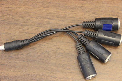
Now we just need some female MIDI cables (or male cables and some couplers), an 8-pin miniDIN cable, and a soldering iron.
FINAL PINOUT
Compared to the lettering on the miniDIN jack picture:
A – IN (to anode — LeftOffset of MIDI cable picture)
B – OUT +5v
C – IN 2 (to anode — LeftOffset of MIDI cable picture)
D – IN (to cathode — RightOffset of the MIDI cable picture)
E – OUT 2 +5v
F – IN 2 (to cathode — RightOffset of the MIDI cable picture)
G – OUT 1 data
H – OUT 2 data
Jack Chassis – both center pins of the OUT cables **
** This method doesn’t create any ground loops because both MIDI cables connected to the OUT jacks never touch any other equipment through the center pins because they are disconnected at the IN of each piece connected. The only things electrically touching are the shields of both OUT cables and the PCI card ground.
Sidenote: Looking at the bottom of the PCI card, we can see that the MIDI jack pins are arranged in 2 rows. If you divide them vertically into 4 pairs, you’ll see that each IN and OUT line up. In other words… (C/F)(A/D)(B/G)(E/H), which is the proper pairing. Since A and C had to be mutually exclusive (couldn’t be part of the same pair), we could have guessed that each pair would have been side-by-side vertically, not horizontally. Not definitive proof by any means, but it should give additional confidence in our measurements.
REAL WORLD MEASUREMENTS
.644 resistance measured to “anode” pin on MIDI jack from pin 3 on IC
.246 resistance measured to “cathode” pin on MIDI jack from pin 3 on IC
3.94v measured at OUT data pins when not in use, fluctuating between 3.90-3.95v when carrying MIDI data
Purely speculation, but this is likely to be the pinout used with the Frontier Design WaveCenter PCI card, as well. The WaveCenter ISA card is likely similar, but not identical, due to the different number of ports in/out ports (1 in/3 out).