This tutorial is based upon: http://analog.no/cms/index.php?option=com_content&view=article&id=55&Itemid=54
Read that article first to understand our goal and the basic procedure.
All credit goes to the original author. I’ve only clarified and expanded upon the method in a step-by-step manner. I hope this will be more useful for less intrepid vintage synthesizer owners.
Things you’ll need:
[essentials]
Medium sized phillips screwdriver
Needle-nose pliers
Super-glue – You’ll need this to repair any broken keys as well as gluing the ends of the rubber cover encasing the aftertouch assembly
Rubbing alcohol – for cleaning various surfaces, higher purity is preferable
Acetone (nail polish remover) – same as above, but only use it on metal
Q-Tips / cloth rags – for applying cleaning solutions
[suggested]
X-Acto knife / utility knife – for removing nylon zip ties
Metal polish – will definitely help on the brass aftertouch strip
1/2″ double-sided tape – since the adhesive in this synth is 25 years old, it most likely will not stay tacky enough after the repair. Narrower tape would be better, but I don’t think it exists.
Towel / sheet – protects the worksurface from the synth, and vice versa
Narrow nylon zip ties – totally optional
— It should go without saying, but unplug this from the wall before you open it up and start tinkering.
— Unscrew the three screws from the plastic left side panel, and the three screws from the plastic right side panel.
— Flip over the synth being careful to rest it in a way that will not break the pitchbender.
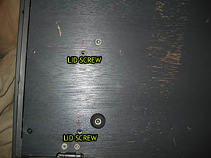
— There are two screws on the bottom that need to be removed before the lid can be lifted up, illustrated below:
— There are also four screws across the bottom edge where the keyboard is. These hold the keyboard assembly in place. Remove these screws.
— Flip the keyboard back over and lift up the lid. On the back edge of the keyboard there are three brass screws holding the keyboard into the wooden base. The one on the farthest left also has a green ground wire connected to it. Remove these screws.
ADVICE: Before disconnecting a plug from its socket, draw an X across the plug and socket with a magic market. Use a different color for each one if you want. This will help you remember where they go, as well as their proper alignment.
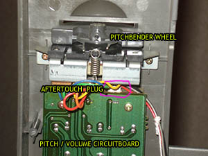
— There is a bundle of wires on the left side of the keyboard assembly leading to the pitchbender circuit on the left side of the lid. Pull the plug out of the pitchbender circuit. If you do not have room to do so, you will need to remove the left side of the lid by removing four screws. You’ll need a screwdriver that is fairly long to reach these. Once that left side is removed you can remove the pitchbender wheel by removing two short brass screws. This will give you space to pull the aftertouch plug out of the pitchbender / volume circuit board.
— There are a few more bundles of wires coming out of the back middle of the keyboard assembly that lead to the mainboard. Unplug these from the mainboard. You may need to remove the long flat ribbon cable for the cartridge reader to gain easy access to those sockets. This can simply be slid straight out of its socket on the top edge of the mainboard.
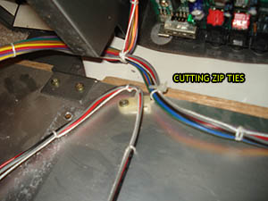
— Now that all the wire bundles connected to the keyboard assembly have been disconnected, you will need to -carefully- cut the zip ties holding the bundles to the wooden base. Pick a point farthest from any of the wires and slowly work away at it, taking care not to cut any of the wires.
— The entire keyboard assembly can now be freed from the chassis. Take care not to abuse the bottom of the keyboard assembly as there are thin metal contact switches which can be bent out of shape or dislodged from their proper positions. If you do happen to displace them, you can usually pop them back into position, or carefully bend them back to their proper shape. They are all in the same configuration, so visually inspect them to make sure they are all uniform.
— Flip the keyboard assembly over (key side down, brass contact side up) and place it on your workbench. You will see that zip ties are looped through white plastic connectors. These connectors can be rotated out of the way, but the wire bundles don’t provide much room. You’ll probably need to remove the zip ties from the middle and right side as well as unplugging the middle and right side sockets on the keyboard circuit board. This will give the wire bundles enough play for you to swivel the zip tie connectors out of the way.
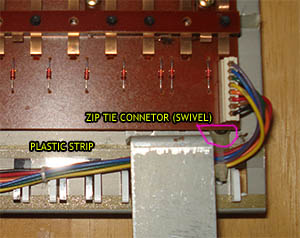
— Now you can remove the long plastic strip that holds the keys from slipping out of place. Just pry up one end and peel it off.
— Flip the keyboard assembly over again, so it’s key side up. You will now have to use needle-nose pliers to remove the key springs. The springs for the white and black keys are different and should be kept separate. Putting them in a baggie or cup is a good idea.
— Remove the keys from the keyboard. This is done by pulling each key towards the front (there’s a metal/rubber finger that goes inside each key) and then lift up. The black keys are pinned down by the surrounding white keys, so do the white keys first. Keep the keys in order so they’ll be easier to reattach after the repair.
— Now is the perfect time to give all the keys a good rubdown with alcohol, or soap and water.
— Each key has two prongs or fingers towards the back (under where the springs would be) which are sometimes broken off or cracked. Occasionally, these broken off bits will even be stuck to the adhesive on the underside of the keyboard assembly. Use superglue to repair any key damage.
— Once the keys have been removed, on the keyboard assembly we can see a long black rubber strip covered with felt. This is the aftertouch assembly. Underneath the black rubber strip is a flexible metal strip. It is not super-fragile, but use caution in the next step. DO NOT SHARPLY BEND OR CREASE THIS METAL STRIP! It is flexible, but take care.
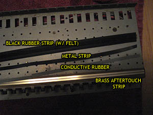
— There is glue on the left and right ends of the black rubber strip keeping it in place. There’s also double-stick tape under the top and bottom edges. Gently free both ends of the rubber strip and peel it off, using caution not to sharply bend the metal strip underneath.
— Remove the metal strip and inspect both sides. You’ll probably find that it’s coated with a rubber-like goop and/or corrosion. Clean both sides with acetone and/or alcohol. You’ll want to be careful while cleaning this. DO NOT USE A BACK AND FORTH RUBBING MOTION. This can cause the strip to bunch up and crease. A good method is to hold one end, and scrub in the opposite direction. So if you’re holding down the right end of the strip, clean it using only motions from right-to-left. Clean until a fresh q-tip won’t be discolored.
— You’ll also see a strip of gray (or white and black striped) conductive rubber. This actually isn’t one long strip, but a bunch of pieces lined up. Remove these rubber strips and give them a good cleaning on both sides. DO NOT USE ACETONE OR ANYTHING THAT CAN DAMAGE RUBBER ON THESE STRIPS! Rubbing alcohol, soap and water, and some scrubbing will probably do the trick.
— Under those conductive rubber strips is the brass aftertouch strip. Clean this off using metal polish if you’ve got it, or some good scrubbing with acetone and rubbing alcohol. Clean until a fresh q-tip won’t be discolored.
— Once the pieces of the aftertouch assembly are all clean and dry, start putting them back together. This can be tricky. One method is to put the conductive rubber strips down on top of the brass aftertouch strip, then place the flexible metal strip on top of those, realigning the rubber strips underneath as needed. Superglue the black rubber cover back in place (just a few drops) on one end, and then stretch the other end back in place and superglue that.
— Wiggle the black rubber strip until the metal strip and conductive rubber underneath are aligned with brass aftertouch strip. All the conductive rubber should be one continuous pieces from end to end, and the metal strip should be lining the whole thing from end to end. Peek under one side of the black rubber strip to see if everything is in place. If not, wiggle some more.
— Once everything looks in place, put double-stick tape under the top and bottom edge of the black rubber strip (assuming it’s no longer tacky after the cleaning we gave it). You can put it right over the top of the old tape. Just pry up each edge, being careful not to push anything out of place again.
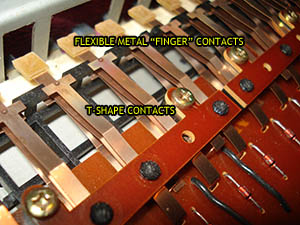
— Repair complete! Now all we have to do is put everything back together and double-check our work. Replace the keys. Put them in the correct order, remembering that the black keys have to go on before the white keys. You’ll see flexible metal contact “fingers” with square yellowish rubber tips that are designed to hit the t-shaped contacts. Make sure the contact fingers are under the keys and not inside them. The key will not be playable unless the contact finger can move down when the key is pressed down. If one of the contacts gets stuck, then the key will be silent and not playable.
— Replace the springs, remembering that the black and white springs are different. Hope you kept those sorted.
— Flip the keyboard assembly over (key side down) and replace the long plastic strip, using double-stick tape or a tiny bit of white glue (if the strip is no longer tacky). This adhesive isn’t really necessary but it’s suggested if you like to be thorough.
— Turn those zip tie swivels back into place. These will pin the long plastic strip down, so make sure it’s in proper position. Put the wire bundles back into position. Replace the zip ties (if it suits you). You’ll also want to reconnect any of those wire bundle plugs to their appropriate sockets on the bottom of the keyboard circuit, or the keyboard will not work at all.
— Triple-check the metal contacts on the underside of the keyboard assembly. Make sure that the fingers contacting the keys are in the proper position. Each should move when the respective key is pressed down. If not, then you’ll have to go back and remove some of the keys again to fix it. Also make sure the t-shaped ones are all uniform. If not, simply pop them back into place.
— Everything else is just putting screws and plugs back in the reverse order we disassembled them. I suggest holding off on replacing the other zip ties until you double-check your work, making sure you have no silent keys and the aftertouch is working properly.
Congratulations, you’ve now got an aftertouch responsive keyboard!


