


The concept of the mod is very simple. Its purpose is to change the input (front & back) so it is better suited for use with line level devices (synthesizers, drum machines, audio interfaces, etc.) as the original design is optimized for instrument level (guitar/bass) signals. Also, the output gain is given a boost, so less makeup gain is needed when connected to recording mixers / audio interfaces.
A common hangup is that people are unsure of what electrical components to get, as modifying gear requires some technical expertise. The original article leaves this open-ended as an almost infinite range and combination of parts could be selected for this modification, so long as they meet the proper electrical specifications. As such, making a parts list is mostly a matter of taste and budget, therefore best left to the individual performing the work. With that said, here is…
WHAT TO BUY, WHAT TO DO, AND HOW TO DO IT
All resistors should be metal film as this is an analog stage mod, and so metal film will have less noise than carbon resistors. The original DE-200 resistors are very tiny, but the extra space on the PCB allows for larger footprint resistors to be used, such as 1/4W, although not the ideal size.
Electrolytic capacitors are polarized and have to be installed properly with respect to positive and negative. However, the capacitors suggested by this guide are not polarized, so they can be installed in either orientation.
The part numbers given can currently be found at Mouser. The suggested components are more expensive (and probably overkill) compared to some other options, but they have been tested to work.
INPUT STAGE
All three of these components are found between IC2 and SW1 BYPASS @ the front of the unit. See picture below for location.
C3 – 4.7uF; WIMA MKS2C044701M00JO00
R10 – 10k; RC55LF-D-10K-B-B (metal film, 1/4W, 0.1%)
R2 – 4.7k; RL07S472GB14 (metal film, 1/4W, 2%)
Note: C3 is a rather tight squeeze, but does fit without alteration.
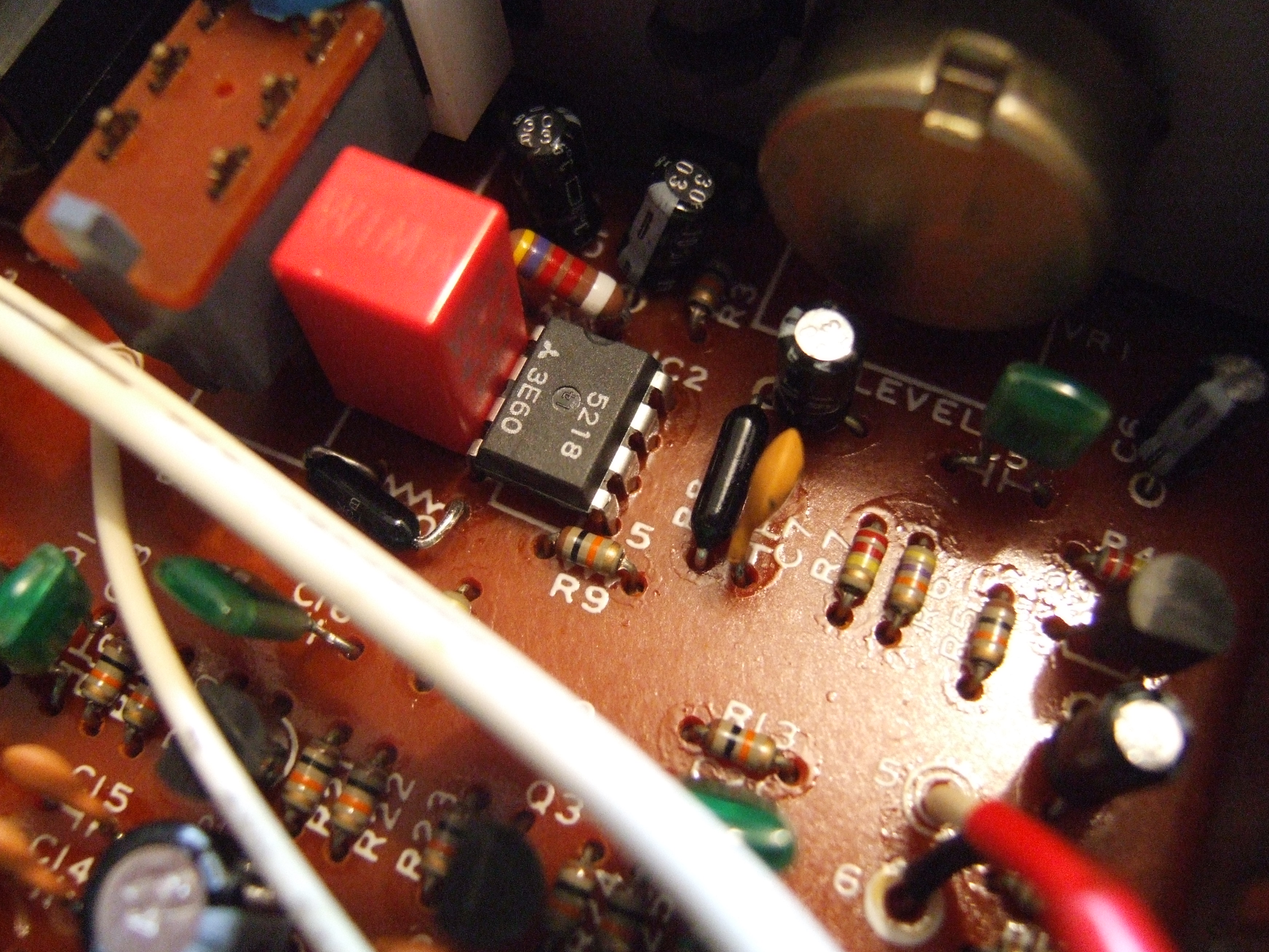
PRE-EMPHASIS
On the other side of IC2, compared to the above components. See picture above for location.
R8 – 110k; RC55LF-D-110K-B-B (metal film, 1/4W, 0.1%)
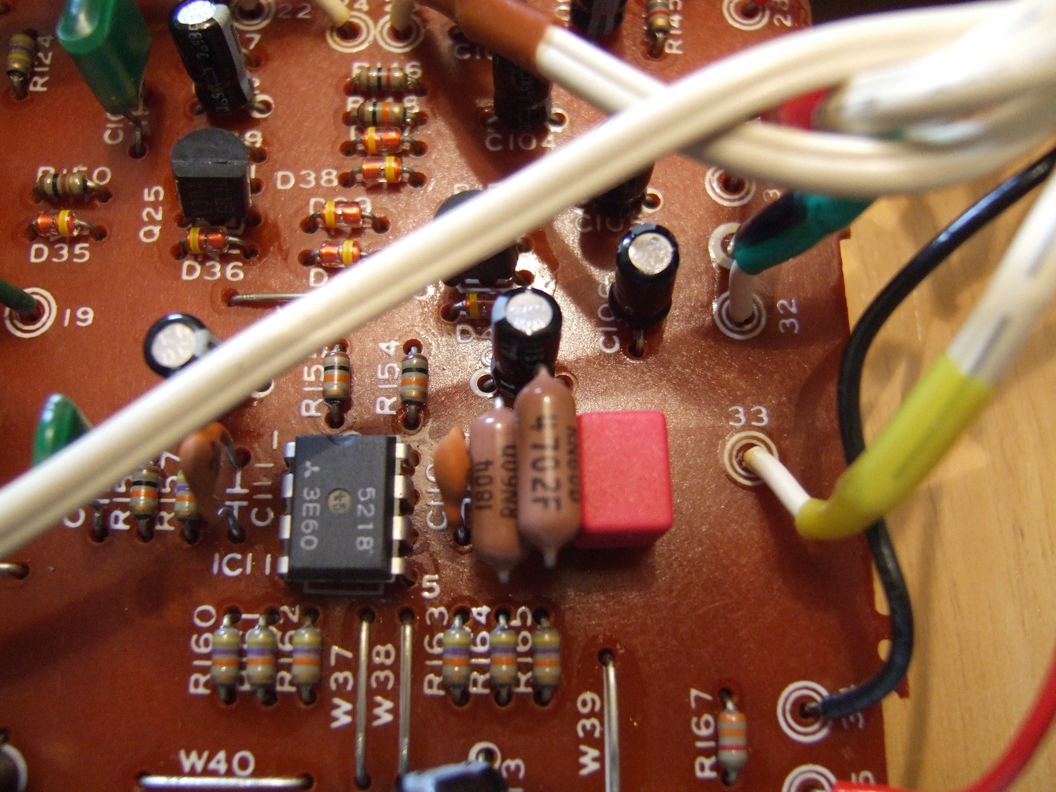
OUTPUT STAGE
On the front output jack board there is a yellow wire #33. All three components are close to where #33 connects to the mainboard.
C109 – 1nF (1000 pF); WIMA FKP2L011001G00JSSD
R159 – 47k; RN60D4702FRE6 (metal film, 1/4W, 1%)
R158 – 220k; RN60D2203FB14 (metal film, 1/4W, 1%)
Tip: Especially with the input stage, it is advisable to remove the capacitors first, and the resistors second. When fitting the new components, place the capacitors first and the resistors last. Make sure all the parts in that area can fit appropriately before committing to soldering.