


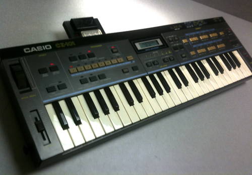
Wicked phase distortion mini-beast from 1984.
If only one key/button isn’t working then you’ve (probably) got an easy fix. The remedy is to check for a physical contaminate or worn-out conductive materials on the button pads. Clean the contacts on the PCB and the rubber buttons themselves. You can apply Caig CaiKote 44 to the buttons to restore them if cleaning doesn’t suffice. If you’re cheap or desperate then scribble some pencil graphite onto the button surface to refresh it. Rubbing alcohol may get rid of surface debris but don’t be too aggressive with it as you don’t want to strip the buttons or contacts of their conductive surface.
If multiple buttons don’t work despite having clean pads and they never work regardless of how hard or vigorously you press them (meaning non-intermittant) then it’s a circuit issue. That can be something physical like a broken pin, bad solder joint, scratched trace or a broken wire, but it can also be something with the logic circuit in an IC (CPU, decoder, etc.)
To determine what the problem is, we must know how the CZ101 reads keys and buttons.
Key Scanning / Key Matrix Basics
As a simple explanation, the keys/buttons on the keyboard are wired into a grid that’s commonly called a keyboard matrix. The CPU or another keyboard controller chip applies current to each column in the matrix while simultaneously checking to see which rows are outputting current. The point at which the active row and column intersect corresponds to which button/key is pressed.
How does the CZ101 actually do this?
The key matrix starts and ends with the CPU.
The CPU first sends four signals (PB0-3) out to the 74LS154 decoder chip. From there the decoder chip generates and outputs sixteen signal lines (called KC signals) which go to both the keybed and the panel buttons.
Note: The decoder never provides any data to the CPU, it only generates column signals to send out to the keys/buttons. How this works will be explained later.
When a button/key is depressed, it closes one of a group of eight circuits (called KI signals). As soon as the button touches the PCB (printed circuit board), the KI signal travels to the 74HC241 tri-state buffer chip where its current state (on or off) is captured by the buffer chip’s input and set accordingly on its output. The CPU reads the buffer output using the data bus (D0-7) and is sent the current KI states which tells the CPU which row buttons are depressed at that moment.
The CPU checks both signals (KC, KI) against each other (through row and column intersection) and figures out which button has been pressed.
The technical implementation sounds very confusing, but the concept is actually very simple. The CPU sequentially energizes each column and then it checks to see if any rows in the active column have been closed. If so, then there’s only one point in the matrix it can be. Since each point matches one and only one button/key, the CPU can very easily tell which button is depressed at that exact instant in time.
What is KC<x>?
That stands for Key Common. So KC1 is Key Common, signal 1. These signal lines form the columns of our key matrix.
What is KI<x>?
Key Input. Mostly the same concept as KC, except they form the rows of the key matrix instead of the columns.
What is the tri-state buffer for?
It actually doesn’t have much functionality in a logical sense. The tri-state buffer does absolutely nothing except reflect the state of keypress data (KI signals) so the CPU can read it; it doesn’t alter the data at all.
How does the CPU figure out what button is pressed when there are only eight signals sent from the tri-state?
Remember, where the KI and KC signals intersect (one row, one column = one entry) determines which button/key is being pressed.
So certain groups of keys share the same KI and/or KC properties, but only one button can have the particular point where a specific row and column cross.
With sixteen KC signals and eight KI signals, the CPU could understand up to 128 unique keys/buttons.
If the CPU never reads from the decoder (KC) but only from the tri-state (KI), how does it know what the current KC values are?
Because the CPU is controlling the decoder already. The CPU doesn’t need any feedback as to what KC signal is being checked because it has master control over which KC signal is currently activated. Whatever KC line the CPU is asking the decoder to generate at that moment is the same KC signal that the CPU will check against the KI values reported by the tri-state.
Okay… well then, how does the CPU know which of the sixteen KC signals intersects with the current KI signal when the CPU is only sending out four signals (PB0-3)?
Good question. Here’s how the decoder works:
The four different signals are read by the decoder simultaneously, but the decoder generates KC signals sequentially. Each signal can be on or off, so given all the different combinations (4^2) we get sixteen KC lines that can possibly be energized. Remember, only one line is actually active at any given moment, so the CPU only has to signal which one out of the sixteen should be fed current; the CPU never controls the state of all sixteen lines at exactly the same time as they are mutually exclusive. In other words, the CPU can tell KC1 to be on but that automatically turns off KC2-16. The CPU will not (and cannot, mathematically) request more than one active KC signal at a time.
If only one KC signal is active at a time, then how can I hold down chords on the note keys?
Technically, the KC signals are sequentially activated but the CPU cycles through the KC lines so extremely quickly that any button presses appear (to our relatively slow senses) to be instantly read.
Say… What are all the diodes by the keys/buttons for?
“Ghosting” is an unwanted phenomenon that occurs when current flows the wrong way around a key matrix and causes a row to output current when it should not. Each button/key has a diode to prevent current “backflow” which eliminates false notes that were never really pressed.
Why do multiple buttons sometimes fail at exactly the same time?
Remember, unless a solitary button or contact fails physically due to dust, being worn out, etc. then there can only be an electrical failure. With our knowledge of KI/KC signals, having an entire row/column fail makes sense as a very common fault. In fact, although possible, an electrical failure will very rarely affect only one key. This is one repercussion of a matrix type system.
For example: KI7 is a shared signal for six buttons: Sustain, Select, Patch #7, Cartridge, DCA1 Key Follow and DCA2 Key Follow. If you were to cut the PCB trace for KI7 before it gets to the tri-state buffer then all of those buttons would stop working.
What ways can entire KI lines fail?
There are many different points of potential failure.
As in the example above, you can have a physically bad trace so that the line can never be closed and any button on that line can never be activated. A bad solder joint on one of the tri-state pins that read the KI lines would have exactly the same result.
A group of buttons can also be stuck on permanently. Once a button appears to be held down, it will be considered by the CPU to be held down until it reads an off KI state from the tri-state buffer. If one of the tri-state buffer pins that report a KI line is stuck permanently on then the CPU will keep that whole corresponding KI key group active forever whether or not any of the buttons were actually pressed.
Likewise, even if a KI signal is getting to the tri-state, if a reporting pin is disconnected or stuck off then the CPU will never register any key in that KI group regardless of how hard or frequently they may be pushed.
What ways can entire KC lines fail?
Quite similarly to KI lines, except involving the CPU or decoder.
If one of the output pins on the decoder is broken and can’t send current then any group of keys tied to that KC line will be unresponsive because none of the KI lines that cross that particular (dead) KC line can carry a signal to the tri-state. Even though the various KI lines may be closed with a button press, the tri-state cannot see a non-energized line. Other buttons on the same KI line will still work, however, because they will be powered by whatever (working) KC line they happen to cross.
Even worse, if any one input pin on the decoder is bad then four KC lines will be bad. Similarly, if any one PB line from the CPU is dead then you’ll get the same result. This is one of the worst cases you can have because all eight KI lines that are fed by each of the four bad KC lines will result in thirty-two dead buttons/keys.
What’s the actual worst case scenario for button/key failure?
Obviously, total CPU/tri-state/decoder failure. Every button dies completely.
The next step down from that is ribbon cable failure, the worst of which is keyboard ribbon cable failure. Given the construction, it’s conceivable that the entire ribbon cable going from the main logic board to the keybed PCB could be sheared off.
If one physical half of the panel buttons don’t work (as opposed to a semi-random scattershot) then you might have a severed ribbon cable from the CN2 board to the CN1 board. Similarly, if you have no panel buttons whatsoever, yet all the music keys still respond then you might have a bad cable from CN1 to MA1.
What are Joiners and which are which?
If you consult the schematics for the CZ101, you will see abbreviations like JA6, JH2, etc. which correspond to the various ribbon cables connecting all the PCBs, as well as individual pins within the ribbon cables.
Example: JG6 = [Joiner cable ‘G’, pin 6]
The schematics show the KC/KI signal paths, the joiner pins from which they leave the mainboard, the joiner pin it arrives on at the other PCB, and then what PCB it arrives on.
If you follow the KC signals from the decoder outputs, they will lead to a couple joiner ribbon cables. Each signal crosses to the other PCBs via its own pin. The KI signals which come back from CN1/CN2/KY are also returned on their own individual pins via joiners.
Example: KC10-16 are sent to CN1 through the JC ribbon. KI7 connects CN1 and CN2 through JG7 and is then returned to MA1 through JC6.
Where are the KC signals routed to?
KC1-9 are routed to the keybed PCB (KY) [9×8 = 72 possible keys]. KC10-16 are routed to the first front panel board (CN1) [7×8 = 56 buttons possible]. KC13-16 cross over to CN2 from CN1 via JG [4×8 = 32 possible buttons]. KC16 is passed from CN2 to KY2 via JI6 [1×8 = 8 possible buttons].
Those are the main points, there are a few other random places KC signals are routed to.
Where are the KI signals routed from?
KI1-8 are returned from CN2 to CN1 via JG. KI1-8 are then returned to MA1 via JC. KI2-6 are returned from KY2 to CN2 via JI.
MATRIX TABLE
KC16 (CN2) = Detune [KI1]
KC16 (KY2) = Line Select [KI2], Ring Mod. [KI3], Noise [KI4], Master Tune Up [KI5], Master Tune Down [KI6], N/A [KI8]
KC16 (MA2) = APO Switch** [KI7]
KC15 (CN2 only) = Initialize [KI1], Octave [KI2], DCO2 Wave [KI3], DCO2 Env. [KI4], DCW2 Key [KI5], DCW2 Env. [KI6], DCA2 Key [KI7], DCA2 Env. [KI8]
KC14 = (CN2) = N/A [KI1], Vibrato [KI2], DCO1 Wave [KI3], DCO1 Env. [KI4], DCW1 Key [KI5], DCW1 Env. [KI6], DCA1 Key [KI7], DCA1 Env. [KI8]
KC13 (CN2 only) = Value Save [KI1], Value Load [KI2], Cursor Left [KI3], Cursor Right [KI4], Down [KI5], Up [KI6], Sustain [KI7], End [KI8]
KC12 (CN1 only) = 1 [KI1], 2 [KI2], 3 [KI3], 4 [KI4], 5 [KI5], 6 [KI6], 7 [KI7], 8 [KI8]
KC11 (CN1) = Solo [KI1], Tone[KI2], Transpose [KI3], Write[KI4], MIDI [KI5], Select [KI7]
KC11 (MA1) = Patch Write Protect Switch** [KI6], ‘P’ button** [KI8]
KC10 (CN1 only) = Portamento On/Off [KI1], Portamento Time [KI2], Vibrato On/Off [KI3], Bend Range [KI4], Preset [KI5], Internal [KI6], Cartridge [KI7], Compare [KI8]
KC1-9 (KY only) = Various Piano Keys [KI2-6]
** See the next question for an explanation.
Are KC/KI signals routed anywhere else besides directly to the button/key PCBs?
Yes, a few places. KI7 and KC16 go between MA1 (main logic board) and MA2 (power/amplification board). You’ll notice that KC16/KI7 in the matrix isn’t a panel button or a piano key but a switch. Here’s why:
The APO switch isn’t a button/key per se, but it works exactly the same way electrically. The only difference is that the switch doesn’t rebound like the rubber buttons/keys, so the circuit stays open or closed semi-permanently instead of momentarily. There’s no difference between a key, button, or a switch as far as what the CPU processes or ‘sees’.
Note: If something happens to either KI7 or KC16, not only will some buttons go dead, but the APO feature will be stuck in the same mode regardless of how the switch is set. You can use this behavior to help troubleshoot.
KC11/KI6 behaves in similar fashion, except for the Patch Write Protect Switch which is on the main logic board (MA1).
KC11/KI8 is for the ‘P’ button on the underside of the CZ101 which is used for resetting the internal patches from ROM after a battery change.
Troubleshooting
Scenario 1:
Suppose you have the following dead buttons: Sustain, Select, 7, Cartridge, DCA1 Key Follow, and DCA2 Key Follow. If we look at the key matrix then we will notice they all share the KI7 line.
We should try testing the APO feature. If the APO feature cannot be toggled then it’s fairly safe to conclude that the entire KI7 signal is faulty. The tri-state chip (pin 15, in this case) would be a good place to start our investigation since the CPU requests the state of the KI signals from the buffer.
If Select and 7 (DCA1/2 Key Follow probably too) are almost instantly lit when the CZ101 is powered up then we can assume the entire KI7 line is stuck in the on position. The most reasonable explanation for that would be that the tri-state buffer is flaky and is telling the CPU that KI7 is active regardless of what it receives from KI7 on pin 15.
Note: If the CZ101 is displaying symptoms consistent with a possibly misbehaving or dead tri-state then you have little to lose by replacing it as it is a very inexpensive part.
If those buttons are not lit at power-up yet still don’t respond to selection then we can imagine a few different causes: There could be a break in the trace leading to pin 15 on the tri-state buffer, pin 15 itself could be bad (cold solder joint), or the KI7 related data line to/from the tri-state to the CPU could be bad–either the trace itself or the pins on the CPU or tri-state.
If we can enable/disable APO then the CPU is detecting KI7 properly, which means it is communicating with the tri-state buffer for the state of KI7. Since the APO switch is on a different PCB than the rest of the dead buttons, we could conclude that there is a problem with the Joiner between MA1 and CN1. Specifically, we should check JC6 (Joiner ‘C’, pin 6) because that pin should carry all KI7 signals (from CN1 and CN2 both) to the tri-state buffer on MA1.
Given that Select, 7, and Cartridge are on CN1 and both DCA Key Follow buttons are on CN2, if we had a situation where the Key Follow buttons were dead but Select and Cartridge were still working then we should suspect the Joiner connecting CN1 and CN2.
Scenario 2:
All keys are unresponsive except for those that share the KC8 line. This would point toward either the decoder not outputting on any pins except for the KC8 pin, or the CPU is stuck on requesting KC8 to be generated by the decoder. It’s theoretically possible for all decoder output pins except KC8 to be broken, but the likelihood of that is very remote. It would make far more sense for a chip to be malfunctioning.
Scenario 3:
If random groups of buttons start and stop working erratically, especially if the cursor starts jumping pages and changing values, or there’s random garbage displayed on the LCD then it could be a power supply/regulation issue. Check the voltages at any regulators, make sure the PCBs have good ground points, and replace all the electrolytic capacitors.
Casio CZ-101 Service Manual and Schematics
For those wishing to explore this at the circuit level themselves, we have made available the complete CZ-101 schematics including the informational portions of the service manual. It should be noted that most versions of the service manual available online are incomplete whereas this version is fully intact.